MCUfriend UNO shield on MEGA2560. Touch problem

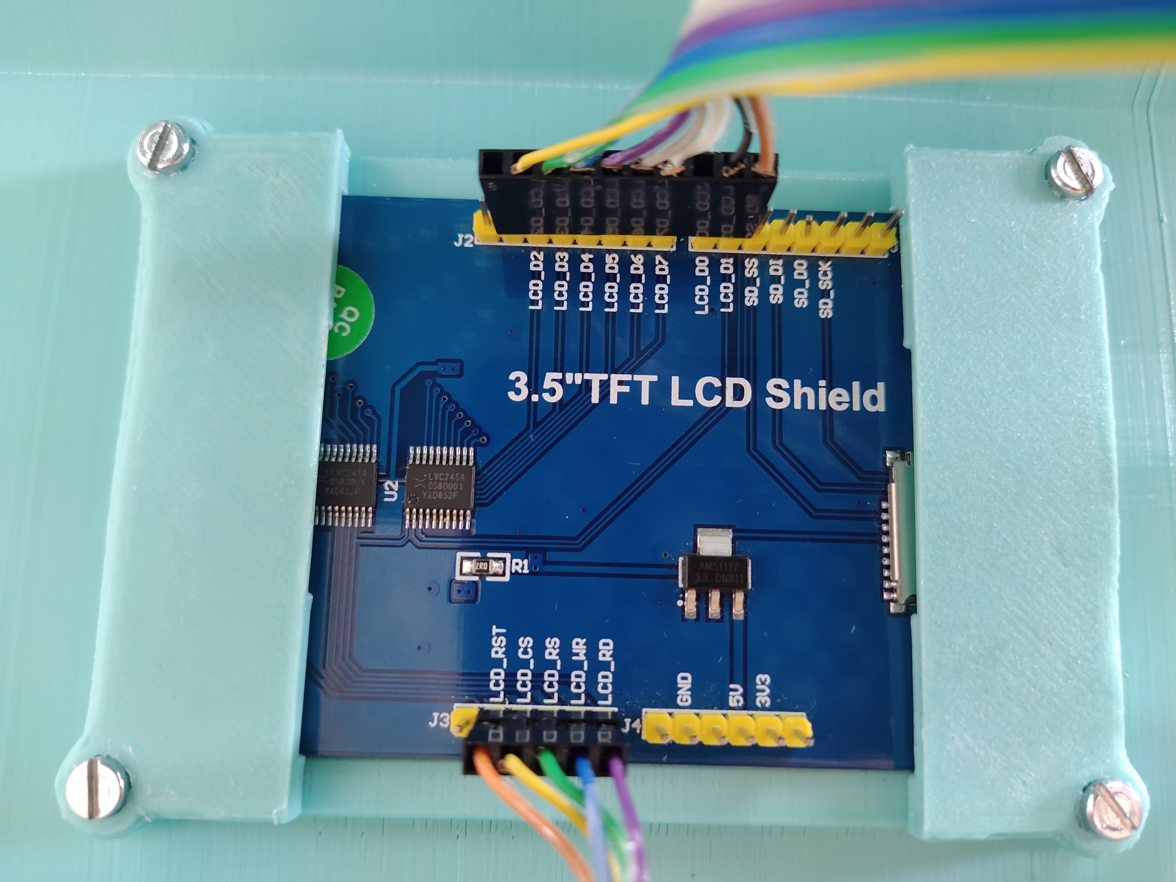
I have a 3.5" MCUfriend TFT shield for Arduino UNO with ILI9486.

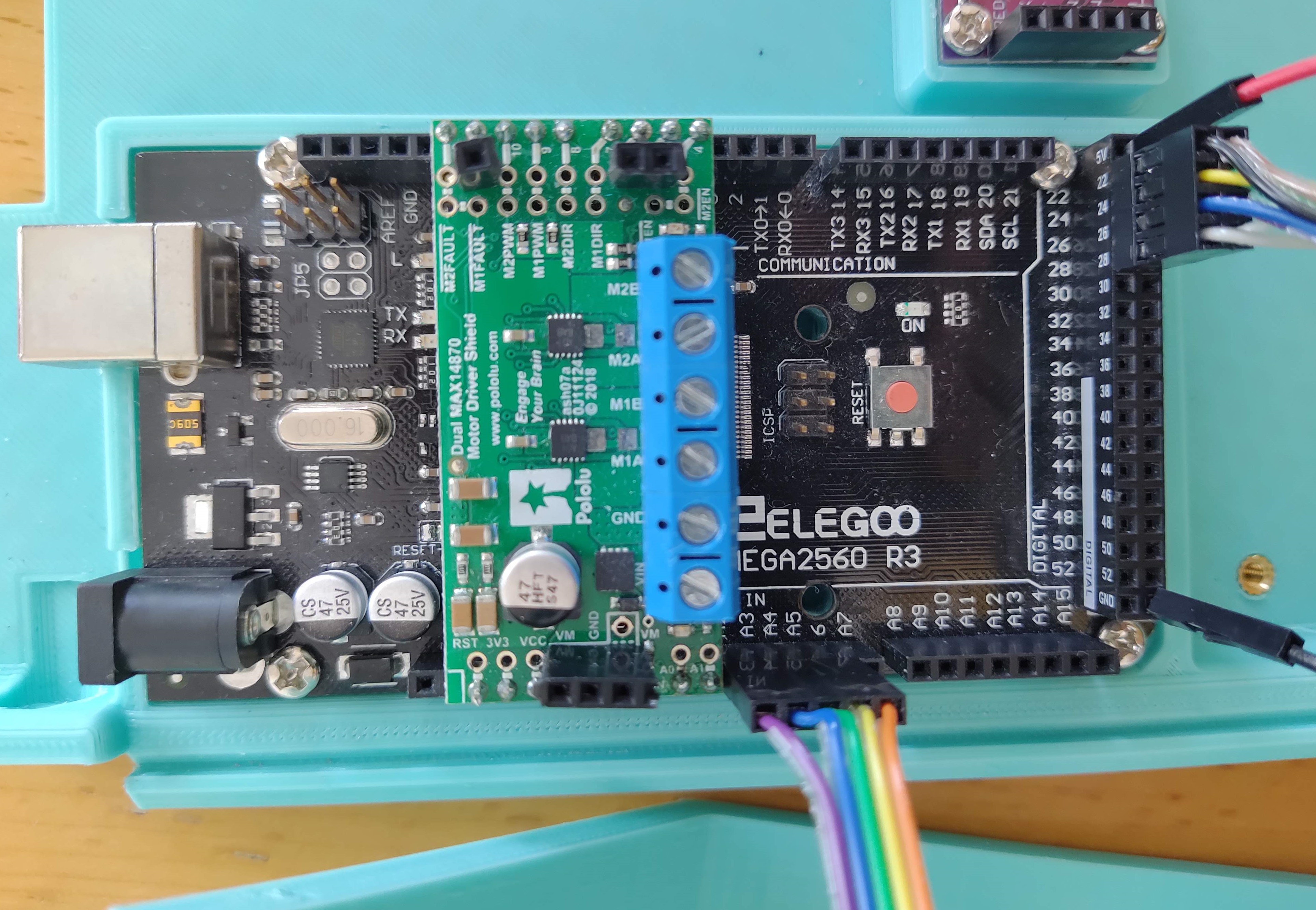
My project use an Arduino Mega2560 and another shield (motor driver Dual max14870), So I need to remap the tft pins for this project.
then I have modified mcufriend_shield.h uncommented the "#define USE_SPECIAL" and likewise
modificate mcufriend_special.h and uncommented "#define USE_MEGA_8BIT_PROTOSHIELD"

Pin remaping:

LCD_D0 22
LCD_D1 23
LCD_D2 24
LCD_D3 25
LCD_D4 26
LCD_D5 27
LCD_D6 28
LCD_D7 29

LCD_RD A2
LCD_ WR A3
LCD_RS A4
LCD_CS A5
LCD_RST A6

When i run "graphictest_kbv" this works perfect. But when i run "button_simple" the button not work.
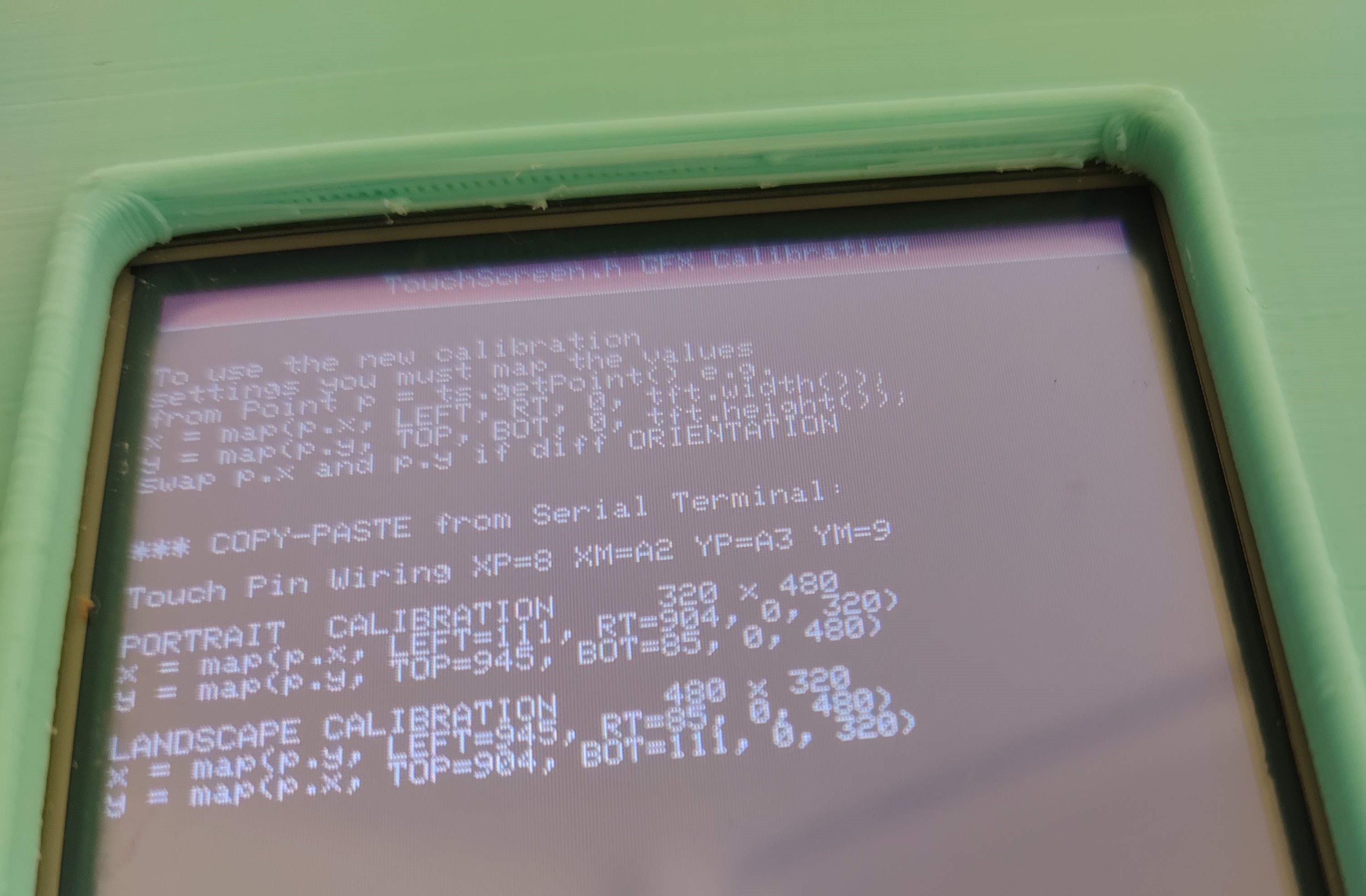
Then i run "TouchScreen_Calibr_native" and appears the next message (Attached image):

Touch Calibration FAILED

Unable to read the position of the press. This is a
hardware issue and can not be corrected in software.
check XP,XM pins with a multimeter
CheckYP, YM pins with a multimeter
should be about 300ohms

I thought the touch pins were broken, so I undid the changes on mcufriend_special.h and mcufriend_shield.h and rewired with original pins (A0,A1,A2,A3,A4 and 2 to 9)

I ran "TouchScreen_Calibr_native" and to my surprise it worked , "button_simple" too .

Any ideas how to fix this? I can't get the touch work, with the pins remapped :confused: :slightly_frowning_face:

In case it is necessary here I paste the result of "LCD_ID_readreg":

Read Registers on MCUFRIEND UNO shield
controllers either read as single 16-bit
e.g. the ID is at readReg(0)
or as a sequence of 8-bit values
in special locations (first is dummy)

reg(0x0000) 00 00 ID: ILI9320, ILI9325, ILI9335, ...
reg(0x0004) 00 54 80 66 Manufacturer ID
reg(0x0009) 00 00 61 00 00 Status Register
reg(0x000A) 00 08 Get Power Mode
reg(0x000C) 00 66 Get Pixel Format
reg(0x0061) 00 00 RDID1 HX8347-G
reg(0x0062) 00 00 RDID2 HX8347-G
reg(0x0063) 00 00 RDID3 HX8347-G
reg(0x0064) 00 00 RDID1 HX8347-A
reg(0x0065) 00 00 RDID2 HX8347-A
reg(0x0066) 00 00 RDID3 HX8347-A
reg(0x0067) 00 00 RDID Himax HX8347-A
reg(0x0070) 00 00 Panel Himax HX8347-A
reg(0x00A1) 00 93 30 93 30 RD_DDB SSD1963
reg(0x00B0) 00 00 RGB Interface Signal Control
reg(0x00B4) 00 00 Inversion Control
reg(0x00B6) 00 02 02 3B 3B Display Control
reg(0x00B7) 00 06 Entry Mode Set
reg(0x00BF) 00 00 00 00 00 00 ILI9481, HX8357-B
reg(0x00C0) 00 0E 0E 0E 0E 0E 0E 0E 0E Panel Control
reg(0x00C8) 00 00 00 00 00 00 00 00 00 00 00 00 00 GAMMA
reg(0x00CC) 00 04 Panel Control
reg(0x00D0) 00 00 00 Power Control
reg(0x00D2) 00 00 00 00 00 NVM Read
reg(0x00D3) 00 00 94 86 ILI9341, ILI9488
reg(0x00D4) 00 00 00 00 Novatek ID
reg(0x00DA) 00 54 RDID1
reg(0x00DB) 00 80 RDID2
reg(0x00DC) 00 66 RDID3
reg(0x00E0) 00 0F 21 1C 0B 0E 08 49 98 38 09 11 03 14 10 00 GAMMA-P
reg(0x00E1) 00 0F 2F 2B 0C 0E 06 47 76 37 07 11 04 23 1E 00 GAMMA-N
reg(0x00EF) 00 80 00 10 60 40 ILI9327
reg(0x00F2) 00 18 A3 12 02 B2 12 FF 10 00 00 00 Adjust Control 2
reg(0x00F6) 00 54 80 66 Interface Control

Here the result of "diagnose_TFT_support"

tft.readID() finds: ID = 0x9486

MCUFRIEND_kbv version: 2.9.8

PORTRAIT is 320 x 480

Thanks

Think about it. Suppose XP, YM are on 6, 7. But you have remapped 6 to 28 and 7 to 29.

If you have the calibration from a regular Arduino, you just change to 28, 29 or whatever.

But the safest way is to edit the Calibration sketch. Where it was testing digital pins 2-9 you should test 22-29.

David.

david_prentice:
Think about it. Suppose XP, YM are on 6, 7. But you have remapped 6 to 28 and 7 to 29.

If you have the calibration from a regular Arduino, you just change to 28, 29 or whatever.

But the safest way is to edit the Calibration sketch. Where it was testing digital pins 2-9 you should test 22-29.

David.

Hello David!, thanks for your quick response

I have tried what you tell me, but the problem continues.

This the modified code of example sketch "TouchScreen_Calibr_native" ( only the first lines):

// TouchScreen_Calibr_native for MCUFRIEND UNO Display Shields
// adapted by David Prentice
// for Adafruit's <TouchScreen.h> Resistive Touch Screen Library
// from Henning Karlsen's original UTouch_Calibration program.
// Many Thanks.
#define USE_SPECIAL
#define PORTRAIT  0
#define LANDSCAPE 1
#define USE_XPT2046   0
#define USE_LOCAL_KBV 1

#define TOUCH_ORIENTATION  PORTRAIT

#if defined(USB_PID) && USB_PID == 0x804E // Arduino M0 Native
#define Serial SerialUSB
#endif

#define SWAP(x, y) { int t = x; x = y; y = t; }

#define TITLE "TouchScreen.h GFX Calibration"
#include <Adafruit_GFX.h>
#include <MCUFRIEND_kbv.h>
MCUFRIEND_kbv tft;

// MCUFRIEND UNO shield shares pins with the TFT.
#if defined(ESP32)
int XP = 27, YP = 4, XM = 15, YM = 14;  //most common configuration
#else
//int XP = 6, YP = A1, XM = A2, YM = 7;  //most common configuration
int XP = 28, YP = A4, XM = A3, YM = 29;  //next common configuration
//int XP=PB7,XM=PA6,YP=PA7,YM=PB6; //BLUEPILL must have Analog for YP, XM
#endif
#if USE_LOCAL_KBV
#include "TouchScreen_kbv.h"         //my hacked version
#define TouchScreen TouchScreen_kbv
#define TSPoint     TSPoint_kbv
#else
#include <TouchScreen.h>         //Adafruit Library
#endif
TouchScreen ts(XP, YP, XM, YM, 300);   //re-initialised after diagnose
TSPoint tp;                            //global point

void readResistiveTouch(void)
{
    tp = ts.getPoint();
    pinMode(YP, OUTPUT);      //restore shared pins
    pinMode(XM, OUTPUT);
    //digitalWrite(YP, HIGH);  //because TFT control pins
    //digitalWrite(XM, HIGH);
    //    Serial.println("tp.x=" + String(tp.x) + ", tp.y=" + String(tp.y) + ", tp.z =" + String(tp.z));
}

the original sketch
XP = 7, YP = A2, XM = A1, YM = 6

Then I tried with:

XP = 28, YP = A4, XM = A3, YM = 29
and
XP = 29, YP = A4, XM = A3, YM = 28

and because the calibration test I did with the usual pins resulted in
XP = 8, YP = A3, XM = A2, YM = 9

I tried too with
XP = 28, YP = A5, XM = A4, YM = 29

But nothing seems to work, the result is "Touch Calibration FAILED"...
I do not know what I'm doing wrong

and because the calibration test I did with the usual pins resulted in
XP = 8, YP = A3, XM = A2, YM = 9

i.e. XP is on LCD_D0, YP is on LCD_CS, XM is on LCD_RS, YM is on LCD_D1 as printed on the shield.

Means your re-mapped wiring needs:

XP = 22, YP = A3, XM = A2, YM = 23

But seriously, if you change the data pins (and/or the control pins) you need to edit the Calibration sketch to test your new data pins in the diagnose_touchpins() function.

David.

Hello David,

This is the pins summary:

LCD.........Original pin.........New pin

LCD_D0.............8................22
LCD_D1.............9................23
LCD_D2.............2................24
LCD_D3.............3................25
LCD_D4.............4................26
LCD_D5.............5................27
LCD_D6.............6................28
LCD_D7.............7................29

LCD_RD............A0...............A2
LCD_WR...........A1...............A3
LCD_CD............A2...............A4
LCD_CS............A3...............A5
LCD_RST...........A4...............A6

when i run "TouchScreen_Calibr_native" with original pins , the results on screen is :

XP.......8
XM.....A2
YP......A3
YM......9

Then the new pins would be (as you commented about XP and YM) :

XP......22
XM......A4
YP......A5
YM......23

So, as expected, if I run "diagnose_Touchpins" with original pins , the results on serial monitor is:

Making all control and bus pins INPUT_PULLUP
Typical 30k Analog pullup with corresponding pin
would read low when digital is written LOW
e.g. reads ~25 for 300R X direction
e.g. reads ~30 for 500R Y direction

Testing: (A2, D8) = 21
Testing: (A3, D9) = 31
Diagnosing as:-
XM, XP: ( A2,D8) = 21
YP, YM: (A3,D9) = 31

The good news is when I run "button_simple" with new pins , the touch works!!! I'm happy for this! (Thanks) , The bad news is I can't calibrate the screen .

Becouse, when I run "TouchScreen_Calibr_native" with new pins, the result on screen is "Touch Calibraton Failed" , and Result on serial monitor is:

TouchScreen.h GFX Calibration
Making all control and bus pins INPUT_PULLUP
Typical 30k Analog pullup with corresponding pin
would read low when digital is written LOW
e.g. reads ~25 for 300R X direction
e.g. reads ~30 for 500R Y direction

MISSING TOUCHSCREEN
ID = 0x9486

and when i run "diagnose_Touchpins" with new pins the result on serial monitor is :

Making all control and bus pins INPUT_PULLUP
Typical 30k Analog pullup with corresponding pin
would read low when digital is written LOW
e.g. reads ~25 for 300R X direction
e.g. reads ~30 for 500R Y direction

nothing more

So, i guess i am not editing the calibration sketch and the diagnostic sketch correctly

Here I paste the first lines of each one with the new pins:

"button_simple" edit with new pins ( This works!) :

#define USE_SPECIAL
#if 1

#include <Adafruit_GFX.h>
#include <MCUFRIEND_kbv.h>
MCUFRIEND_kbv tft;
#include <TouchScreen.h>
#define MINPRESSURE 200
#define MAXPRESSURE 1000

// ALL Touch panels and wiring is DIFFERENT
// copy-paste results from TouchScreen_Calibr_native.ino
const int XP = 22, XM = A4, YP = A5, YM = 23; //ID=0x9341
const int TS_LEFT = 224, TS_RT = 896, TS_TOP = 830, TS_BOT = 87;

TouchScreen ts = TouchScreen(XP, YP, XM, YM, 300);

Adafruit_GFX_Button on_btn, off_btn;

int pixel_x, pixel_y;     //Touch_getXY() updates global vars
bool Touch_getXY(void)
{
    TSPoint p = ts.getPoint();
    pinMode(YP, OUTPUT);      //restore shared pins
    pinMode(XM, OUTPUT);
    digitalWrite(YP, HIGH);   //because TFT control pins
    digitalWrite(XM, HIGH);
    bool pressed = (p.z > MINPRESSURE && p.z < MAXPRESSURE);
    if (pressed) {
        pixel_x = map(p.x, TS_LEFT, TS_RT, 0, tft.width()); //.kbv makes sense to me
        pixel_y = map(p.y, TS_TOP, TS_BOT, 0, tft.height());
    }
    return pressed;
}

"TouchScreen_Calibr_native" edit with new pins (not work) :

#define USE_SPECIAL

#define PORTRAIT  0
#define LANDSCAPE 1
#define USE_XPT2046   0
#define USE_LOCAL_KBV 1

#define TOUCH_ORIENTATION  PORTRAIT

#if defined(USB_PID) && USB_PID == 0x804E // Arduino M0 Native
#define Serial SerialUSB
#endif

#define SWAP(x, y) { int t = x; x = y; y = t; }

#define TITLE "TouchScreen.h GFX Calibration"
#include <Adafruit_GFX.h>
#include <MCUFRIEND_kbv.h>
MCUFRIEND_kbv tft;

// MCUFRIEND UNO shield shares pins with the TFT.
#if defined(ESP32)
int XP = 27, YP = 4, XM = 15, YM = 14;  //most common configuration
#else
//int XP = 6, YP = A1, XM = A2, YM = 7;  //most common configuration
int XP = 22, YP = A5, XM = A4, YM = 23;  //next common configuration
//int XP=PB7,XM=PA6,YP=PA7,YM=PB6; //BLUEPILL must have Analog for YP, XM
#endif
#if USE_LOCAL_KBV
#include "TouchScreen_kbv.h"         //my hacked version
#define TouchScreen TouchScreen_kbv
#define TSPoint     TSPoint_kbv
#else
#include <TouchScreen.h>         //Adafruit Library
#endif
TouchScreen ts(XP, YP, XM, YM, 300);   //re-initialised after diagnose
TSPoint tp;                            //global point

void readResistiveTouch(void)
{
    tp = ts.getPoint();
    pinMode(YP, OUTPUT);      //restore shared pins
    pinMode(XM, OUTPUT);
    //digitalWrite(YP, HIGH);  //because TFT control pins
    //digitalWrite(XM, HIGH);
    //    Serial.println("tp.x=" + String(tp.x) + ", tp.y=" + String(tp.y) + ", tp.z =" + String(tp.z));
}

"diagnose_Touchpins" edit with new pins (not work) :

#include <MCUFRIEND_kbv.h>
MCUFRIEND_kbv tft;
#define USE_SPECIAL


void showpins(int A, int D, int value, const char *msg)
{
    Serial.print(msg);
    Serial.print(" (A" + String(A - A0) + ", D" + String(D) + ") = ");
    Serial.println(value);
}

For this one, just add " #define USE_SPECIAL" , I did not know what else to modify.

Thank you very much for your kindness

Looking at the diagnose_pins() function:

bool diagnose_pins()
{
    ...
    for (i = 2; i < 10; i++) pinMode(i, INPUT_PULLUP);
    for (i = A0; i < A4; i++) {
        pinMode(i, INPUT_PULLUP);
        for (j = 5; j < 10; j++) {
            ...
}

you would alter the data pin statements e.g.

bool diagnose_pins()
{
    ...
    for (i = 22; i < 30; i++) pinMode(i, INPUT_PULLUP);
    for (i = A0; i < A4; i++) {
        pinMode(i, INPUT_PULLUP);
        for (j = 22; j < 30; j++) {
            ...
}

Untested. I just typed in the Browser.

Seriously. The library is intended for people with ready-made Uno shields to plug into ready-made Arduino header sockets.
If a punter wants to customise then she should be prepared to do some work.

Yes, I see that I only test data pins from 5 to 9. Because Uno shields tend to have Touch pins either on 6,7 or on 8,9. You need to test all data pins from 22 to 29.

David.

Now it works correctly!
thanks a lot, David!

With what you told me, I just had to add A6 in the diagnose_pins () function to make it work, as follows:

bool diagnose_pins()
{
    ...
    for (i = A0; i < A6; i++) pinMode(i, INPUT_PULLUP);
    for (i = 22; i < 30; i++) pinMode(i, INPUT_PULLUP);
    for (i = A0; i < A6; i++) {
        pinMode(i, INPUT_PULLUP);
        for (j = 22; j < 30; j++) {
            ...
}

Problem solved! :smiley:
You're like a legend of TFT screens. Thank you so much!

My apologies. I assumed you were using the regular A0-A4 shield pins for control pins.
i.e. I expected you to use the ready-made USE_MEGA_8BIT_PROTOSHIELD special

My bad for not reading your post carefully.

I am pleased that you are working ok now.

David.