Hi!
I need to measure frequency on a power wires.
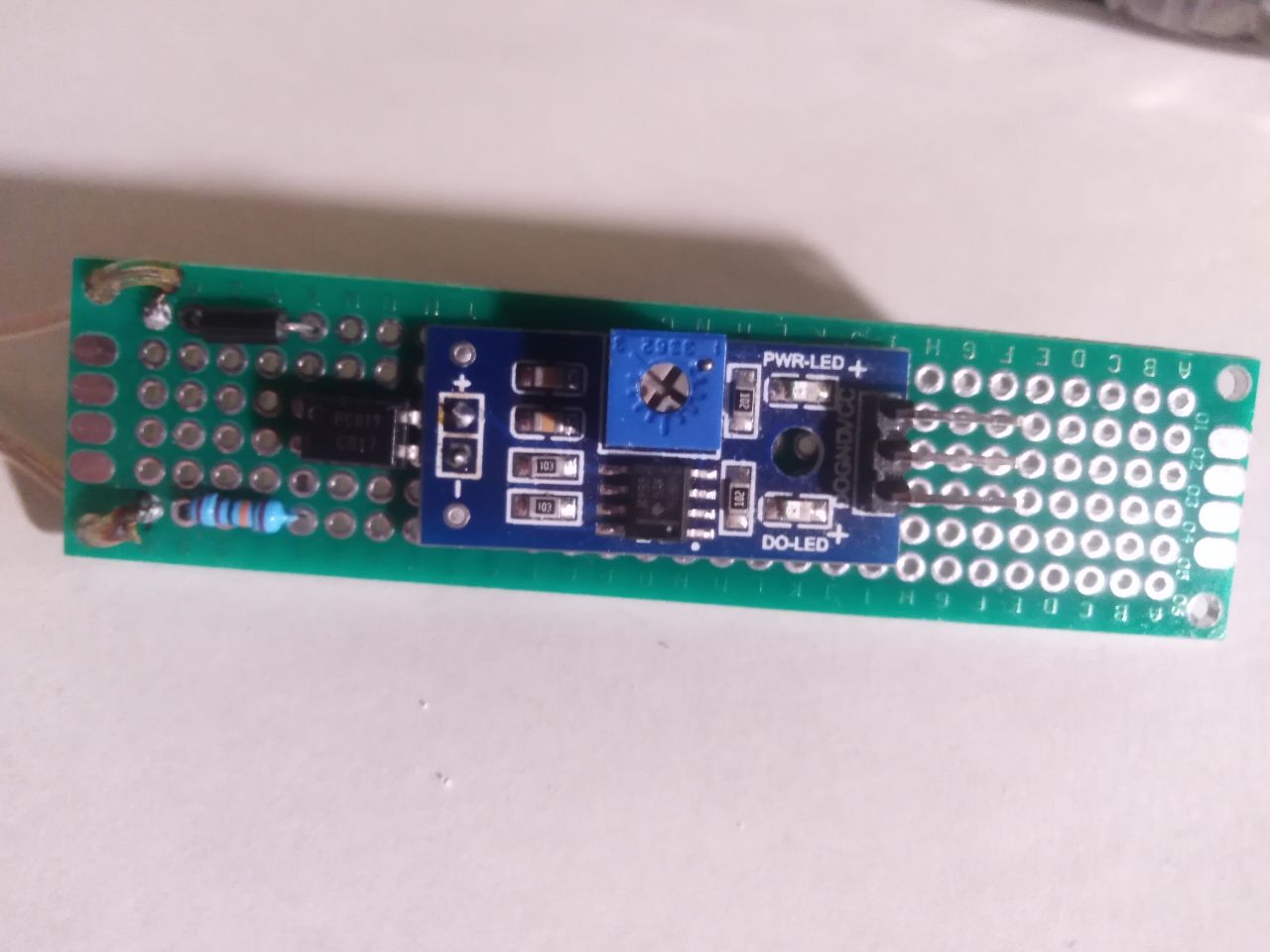
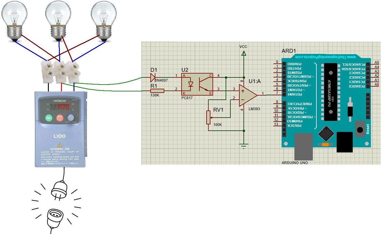
What i have: Arduino UNO, frequency converter Hitachi L100 (with 3 light bulb`s connected on a delta) and PC817 + LM358.
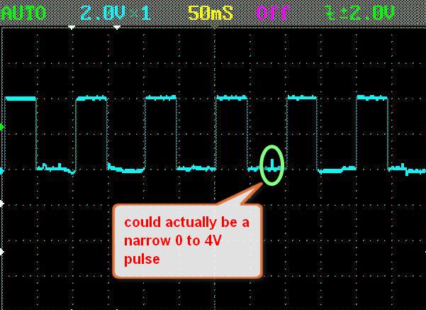
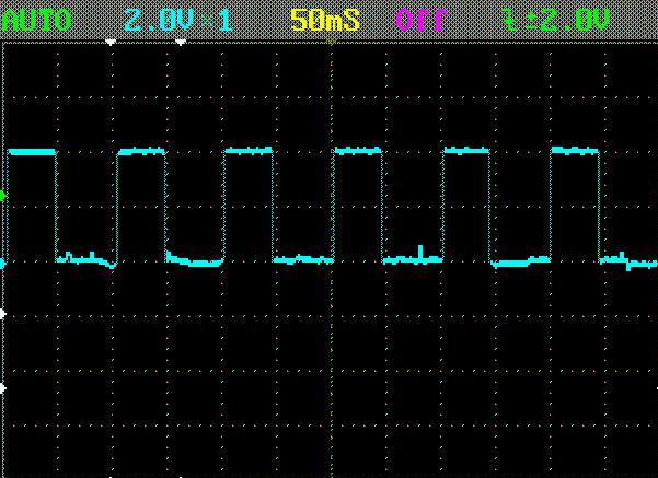
After LM358 signal looks like that (frequency 10 Hz):
I`m using standard code to function pulseIn(). (i have tried to pullup input pin. Wait LOW and HIGH signal...)
But on the serial monitor i have total garage. Random numbers, from zero to five thousand.
Not really. You seem to have modified an LDR sensor module. Please post all the details of the module and how you adapted it. I think we may be looking at this.
Please post complete information about your project activities.
Please clear up the discrepancies. You mentioned an LM358 but the schematic you posted, and a subsequent reference to LM393.
As I don't know this oscilloscope, and I didn't understand your image.
Is the screen at 2V per division, or does the indication say that the pulse has an amplitude of 2V?
Thank you all, for helping me to solve this issue.
2 aarg: Yes. I have tried to adjust RV1. And do it with oscilloscope.
2 TomGeorge: Hi. I`m from Ukraine. We all love British people. (especially Boris Johnson).
I have external pullup 10K (I forgot to described on circuit diagram). And I have tried internal pullup.
2 aarg: Yes. You right. But not LDR sensor module. Its NTC sensor module. And I check it on the oscilloscope. The scheme I described is the same to yours. (circuit that I draw dont have 2 LEDs, and R2 in my case is 100K. Also 2 filter capacitance).
But you are right.
2 david_2018: Frequency converter generates a sinusoidal signal, so it doesn't matter.
2 LarryD: I have tried like this, at the start. But signal is noisy. With Schmitt trigger signal is more clear.
2 ruilviana: DSO NANO V3. Its a trigger for "signal searching mode". In "AUTO mode" this trigger doesn't meaning anything.
It seems like you have done everyhing right but yet it is not working.
My guess is that here are very narrow noise spikes in the signal that won't be captured by the DSO nano scope. It only has a 200kHz bandwidth so narrow spikes that will trigger the UNO pulseIn input may not be seen on that scope.
What do you mean "rising or falling" ? The down arrow is for falling edge only !
I don't understand the signification of the ± symbol and your explanation is wrong even though a -2V trigger level doesn't make sense with a 0-4V signal.
But what will the scope show if I want to trigger at -2V (with the appropriate signal of course) ?

![Light Sensing Module - LDR [4589] : Sunrom Electronics](https://europe1.discourse-cdn.com/arduino/original/4X/d/d/2/dd25556b03fc66c729b09a6eb0a8a7ddffd9f17b.gif)