MFRC RC522 not communicating with arduino uno

so i am working on an rfid based attendance system but before that i wanted to check my rfid rc522... i installed mfrc522 library and used dumpinfo example code.... i get this output on serial monitor... firmware version: 0x0 = unknown
Warning : Communication failure, Is MFRC522 connected properly?
Scan PICC to see UID, SAK, type, and data blocks...

My arduino uno shows yellow light when connected through USB and a red light in RC522 module lights up with D1..........its not taking input...its not scanning the card....I connected mu arduino uno to rfid directly through male to female jumper wires.....Checked the connections multiple times... this is the dumpinfo code:

`/*
 * --------------------------------------------------------------------------------------------------------------------
 * Example sketch/program showing how to read data from a PICC to serial.
 * --------------------------------------------------------------------------------------------------------------------
 * This is a MFRC522 library example; for further details and other examples see: https://github.com/miguelbalboa/rfid
 * 
 * Example sketch/program showing how to read data from a PICC (that is: a RFID Tag or Card) using a MFRC522 based RFID
 * Reader on the Arduino SPI interface.
 * 
 * When the Arduino and the MFRC522 module are connected (see the pin layout below), load this sketch into Arduino IDE
 * then verify/compile and upload it. To see the output: use Tools, Serial Monitor of the IDE (hit Ctrl+Shft+M). When
 * you present a PICC (that is: a RFID Tag or Card) at reading distance of the MFRC522 Reader/PCD, the serial output
 * will show the ID/UID, type and any data blocks it can read. Note: you may see "Timeout in communication" messages
 * when removing the PICC from reading distance too early.
 * 
 * If your reader supports it, this sketch/program will read all the PICCs presented (that is: multiple tag reading).
 * So if you stack two or more PICCs on top of each other and present them to the reader, it will first output all
 * details of the first and then the next PICC. Note that this may take some time as all data blocks are dumped, so
 * keep the PICCs at reading distance until complete.
 * 
 * @license Released into the public domain.
 * 
 * Typical pin layout used:
 * -----------------------------------------------------------------------------------------
 *             MFRC522      Arduino       Arduino   Arduino    Arduino          Arduino
 *             Reader/PCD   Uno/101       Mega      Nano v3    Leonardo/Micro   Pro Micro
 * Signal      Pin          Pin           Pin       Pin        Pin              Pin
 * -----------------------------------------------------------------------------------------
 * RST/Reset   RST          9             5         D9         RESET/ICSP-5     RST
 * SPI SS      SDA(SS)      10            53        D10        10               10
 * SPI MOSI    MOSI         11 / ICSP-4   51        D11        ICSP-4           16
 * SPI MISO    MISO         12 / ICSP-1   50        D12        ICSP-1           14
 * SPI SCK     SCK          13 / ICSP-3   52        D13        ICSP-3           15
 *
 * More pin layouts for other boards can be found here: https://github.com/miguelbalboa/rfid#pin-layout
 */

#include <SPI.h>
#include <MFRC522.h>

#define RST_PIN         9          // Configurable, see typical pin layout above
#define SS_PIN          10         // Configurable, see typical pin layout above

MFRC522 mfrc522(SS_PIN, RST_PIN);  // Create MFRC522 instance

void setup() {
	Serial.begin(9600);		// Initialize serial communications with the PC
	while (!Serial);		// Do nothing if no serial port is opened (added for Arduinos based on ATMEGA32U4)
	SPI.begin();			// Init SPI bus
	mfrc522.PCD_Init();		// Init MFRC522
	delay(4);				// Optional delay. Some board do need more time after init to be ready, see Readme
	mfrc522.PCD_DumpVersionToSerial();	// Show details of PCD - MFRC522 Card Reader details
	Serial.println(F("Scan PICC to see UID, SAK, type, and data blocks..."));
}

void loop() {
	// Reset the loop if no new card present on the sensor/reader. This saves the entire process when idle.
	if ( ! mfrc522.PICC_IsNewCardPresent()) {
		return;
	}

	// Select one of the cards
	if ( ! mfrc522.PICC_ReadCardSerial()) {
		return;
	}

	// Dump debug info about the card; PICC_HaltA() is automatically called
	mfrc522.PICC_DumpToSerial(&(mfrc522.uid));
}`

I did surf the net for troubleshooting ...some recommended to use level shifters and some said to solder.........my header pins of RFID RC522 are soldered but i was concerned what if they are not soldered correctly.....

this is my setup:

this is the soldering of header pins

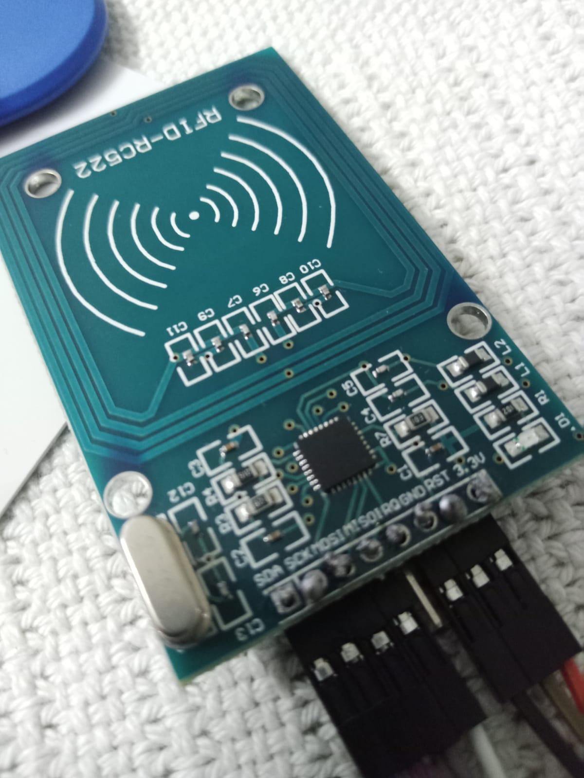
plz if anyone could help resolve this issue....thankyou

Re-work all of your soldering. You have practically no flow, no 'wetting'.

the connections are correct as mentioned in the example and I connected to 3.3v of arduino uno to 3.3v of RC522 module moreover I connected GND of arduino uno to GND of RFD RC522 Module........

Doesn't matter - the soldering job as photo'd is unacceptable (bad).

Thank you for replying...I really appreciate...should I buy a new module and get it soldered or can I resolder this?

Yes, re-solder it. (That's what 're-work' means.)

  1. Your soldering needs to be redone properly.

  2. You've hooked a 3.3V peripheral up to a 5V board. Even if you used 3.3V for the power, the signals are still going to be 5V and the RC522 IC is not 5V tolerant. Don't believe me? Internet says it's fine? Read the datasheet and decide for yourself.

I was also thinking about this ..actually I am new to all this...we were given a short project to make without any guidance so I followed a YouTube tutorial and they just simply connected things...and now I am encountering problems...I'll work on this

I should use level shifters, right? And if I have to use level shifters should I also use an external power supply?

Or is there any other way to deal with this voltage issue?

If you want to use a board that runs at 5V, you need level shifters of some sort to communicate with a 3.3V peripheral. At the very least, a resistor voltage divider. At SPI speeds, I prefer an active solution with something like an 74AHC125 myself, but YMMV.

This circuit uses the 5V pin as an input to a 3.3V LDO regulator to avoid relying on the Arduino's 3.3V output having enough current capability for the peripheral. It may be overkill in this case, but it certainly doesn't hurt.

So you used external power supply and a level shifter...Could you please share more details about the power supply you used, such as the voltage and current rating? I'm trying to set up a similar configuration and would appreciate any insights you can provide.

I used a L4931CZ33 because I had it on hand and at up to 250mA output current, it's more than enough for many jobs.

I do have an idea that l4931CZ33 is a voltage regulator but I am having trouble finding info on how to use it in the diagram my project like I don't know how to connect it or stuff ...moreover I would like to know which type of power source to use like can I use a battery...if yes, what should be the power of it and how can I use it with the l4931CZ33...

To be specific can you give a diagram or details onbwhat power source to use how to connect it to l4931CZ33 and how to further connect this part to the diagram you provided before....

It's my first course in digital electronics so I find it a bit confusing....I appreciate all the help you have provided...

There's an example test circuit on page 4 of the datasheet that shows the hookup and recommended capacitors.

And a quick Google of "how to use a voltage regulator" popped up literally hundreds of articles, 3 chosen at random are shown below.

@Grumpy_Mike can you assist me more with using logic level shifters and voltage regulators. Are there any alternatives to it that could provide the same functionality?

OK. Well for voltage regulators then I would advise reading the links posted by @van_der_decken and then coming back and explain exactly what you are not understanding. There are many different types of voltage regulators, and the links describe just the simplest type. They are called linear regulators and they reduce the voltage, by burning off the excess power turning it into heat. So in some circumstances they will need a heat sink, or bigger capacity regulator.

As to level shifters they reduce or increase the voltage of a signal depending on the direction of signal flow in a circuit. So unlike a regulator they have very little in the way of current capacity, normally just a few mA or so. You can make a level shifter with two junction transistors or two FETs. Or you can buy them from many places like here:-

I am assuming that you have re-soldered the joints, please provide a new picture showing this has been done.

@Grumpy_Mike I have resoldered my RFID module.

Its working now,like now I am not getting that error and i also tested my original code and its working perfect. thank you all!! i have ordered my voltage regulators and stuff and i'll be sure to add them ...but i have another query...currently i am working with direct connections...i got the voltage of my arduino and rfid checked through a voltmeter...my arduino was recieving only 3.5 to 4 volts while rfid was getting around 2 volts....if the voltage level is low why is it working so fine? shouldn't it give communication errors or could it be that maybe the person may have checked it wrong???

Guess it's not an issue for you this time with the corrected soldering, just careful also about the other side of soldering mistakes, soldering bridges. If you look closely (I have a very big PC monitor) between GND and RST you'll see that you almost soldered those two connections together.
Just something to be aware of for next time.