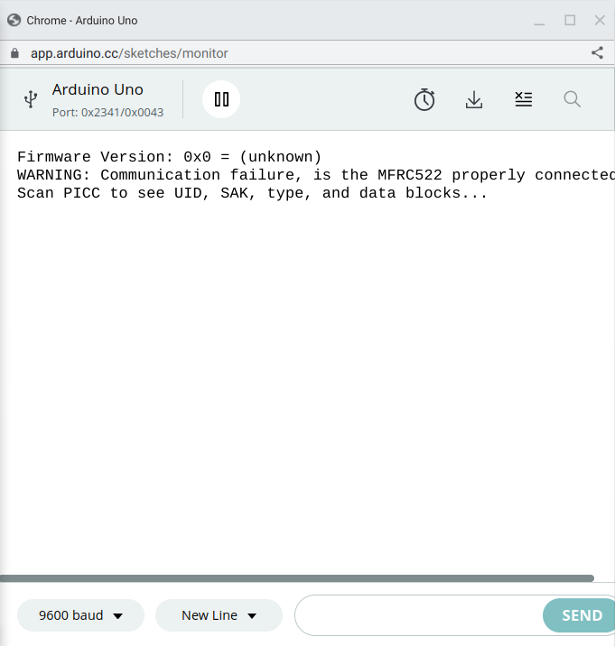
I have a MFRC522 but when I try to read the tag it does not disply anything in the serial monitor. It only displays this at the start of the program:
With the information you posted, only if you have RX vision could we help you.
Do yourself a favor:
Read the topic:
and redo your post.
1 Like
Sorry @ruilviana , I'm very new to this. So I have the arduino UNO R3 and I have uploaded the MFRC522 library example "DumpInfo":
And in case you need it, the code.
#include <SPI.h>
#include <MFRC522.h>
#define RST_PIN 9 // Configurable, see typical pin layout above
#define SS_PIN 10 // Configurable, see typical pin layout above
MFRC522 mfrc522(SS_PIN, RST_PIN); // Create MFRC522 instance
void setup() {
Serial.begin(9600); // Initialize serial communications with the PC
while (!Serial); // Do nothing if no serial port is opened (added for Arduinos based on ATMEGA32U4)
SPI.begin(); // Init SPI bus
mfrc522.PCD_Init(); // Init MFRC522
delay(4); // Optional delay. Some board do need more time after init to be ready, see Readme
mfrc522.PCD_DumpVersionToSerial(); // Show details of PCD - MFRC522 Card Reader details
Serial.println(F("Scan PICC to see UID, SAK, type, and data blocks..."));
}
void loop() {
// Reset the loop if no new card present on the sensor/reader. This saves the entire process when idle.
if ( ! mfrc522.PICC_IsNewCardPresent()) {
return;
}
// Select one of the cards
if ( ! mfrc522.PICC_ReadCardSerial()) {
	return;
}

// Dump debug info about the card; PICC_HaltA() is automatically called
mfrc522.PICC_DumpToSerial(&(mfrc522.uid));
}
and I have this schematic:

Does that help?
Your Uno R3 is a 5V board. It uses 5V level signals.
The RC522 is a 3.3V board. It uses 3.3V level signals.
I don't see any level shifting between the two. That's a problem.
So if I connect it to the 3.3V pin it should work? If not how do I fix it.
You need to shift the 5V output level signals from the Uno R3 to 3.3V level signals before they get to the RC522. A 74AHC125 is suitable for the task. It ends up looking something like this:

I don't have a lot of money. Can I use something like a series of resistor or something to do the same thing?
I use them at 5V all the time. The board is 5V tolerant, if not ideal.
Last Minute Engineers has this to say
The module’s operating voltage ranges from 2.5 to 3.3V, but the good news is that the logic pins are 5-volt tolerant, so we can easily connect it to an Arduino or any 5V logic microcontroller without using a logic level converter.
source:
https://lastminuteengineers.com/how-rfid-works-rc522-arduino-tutorial/#google_vignette
To the OP, are you using the current library?
Let's see your wiring diagram, and post your full sketch using code tags, please.
If you say so. The datasheet says otherwise.

The code
/*
-
- Example sketch/program showing how to read data from a PICC to serial.
-
- This is a MFRC522 library example; for further details and other examples see: GitHub - miguelbalboa/rfid: Arduino RFID Library for MFRC522
- Example sketch/program showing how to read data from a PICC (that is: a RFID Tag or Card) using a MFRC522 based RFID
- Reader on the Arduino SPI interface.
- When the Arduino and the MFRC522 module are connected (see the pin layout below), load this sketch into Arduino IDE
- then verify/compile and upload it. To see the output: use Tools, Serial Monitor of the IDE (hit Ctrl+Shft+M). When
- you present a PICC (that is: a RFID Tag or Card) at reading distance of the MFRC522 Reader/PCD, the serial output
- will show the ID/UID, type and any data blocks it can read. Note: you may see "Timeout in communication" messages
- when removing the PICC from reading distance too early.
- If your reader supports it, this sketch/program will read all the PICCs presented (that is: multiple tag reading).
- So if you stack two or more PICCs on top of each other and present them to the reader, it will first output all
- details of the first and then the next PICC. Note that this may take some time as all data blocks are dumped, so
- keep the PICCs at reading distance until complete.
- @license Released into the public domain.
- Typical pin layout used:
-
-
MFRC522 Arduino Arduino Arduino Arduino Arduino -
Reader/PCD Uno/101 Mega Nano v3 Leonardo/Micro Pro Micro - Signal Pin Pin Pin Pin Pin Pin
-
- RST/Reset RST 9 5 D9 RESET/ICSP-5 RST
- SPI SS SDA(SS) 10 53 D10 10 10
- SPI MOSI MOSI 11 / ICSP-4 51 D11 ICSP-4 16
- SPI MISO MISO 12 / ICSP-1 50 D12 ICSP-1 14
- SPI SCK SCK 13 / ICSP-3 52 D13 ICSP-3 15
- More pin layouts for other boards can be found here: GitHub - miguelbalboa/rfid: Arduino RFID Library for MFRC522
*/
#include <SPI.h>
#include <MFRC522.h>
#define RST_PIN 9 // Configurable, see typical pin layout above
#define SS_PIN 10 // Configurable, see typical pin layout above
MFRC522 mfrc522(SS_PIN, RST_PIN); // Create MFRC522 instance
void setup() {
Serial.begin(9600); // Initialize serial communications with the PC
while (!Serial); // Do nothing if no serial port is opened (added for Arduinos based on ATMEGA32U4)
SPI.begin(); // Init SPI bus
mfrc522.PCD_Init(); // Init MFRC522
delay(4); // Optional delay. Some board do need more time after init to be ready, see Readme
mfrc522.PCD_DumpVersionToSerial(); // Show details of PCD - MFRC522 Card Reader details
Serial.println(F("Scan PICC to see UID, SAK, type, and data blocks..."));
}
void loop() {
// Reset the loop if no new card present on the sensor/reader. This saves the entire process when idle.
if ( ! mfrc522.PICC_IsNewCardPresent()) {
return;
}
// Select one of the cards
if ( ! mfrc522.PICC_ReadCardSerial()) {
	return;
}

// Dump debug info about the card; PICC_HaltA() is automatically called
mfrc522.PICC_DumpToSerial(&(mfrc522.uid));
}
Everyone says so. I don't know what to say about the datasheet, you're right according to it, no arguing that. But it works just fine electrically on an Uno R3
The RC522 has an operating voltage between 2.5V to 3.3V and hence is normally powered by 3.3V and should be used with 3.3V communication lines. But, the communication pins of this module are 5V tolerant and hence it can be used with 5V microcontrollers also like Arduino without any additional hardware. The module supports SPI, IIC and UART communication but out of these SPI is often used since it is the fasted with a maximum data rate of 10Mbps.
source
https://components101.com/wireless/rc522-rfid-module
Edit: just to be clear, the Arduino 3.3V pin powers the MFRC522 but other lines are fine with 5V logic, in case that wasn't clear as I explained it before.
No, post your code properly using code tags (in the IDE, under "Edit" there's an option to copy for forum).
Does your wiring follow the schematic exactly?
Did you solder the RFID board yourself?
What kind of tag are you trying to read? One of the ones that came with the reader?
I just used what I believe to be the same sketch from the same library in both v1.4.9 and 1.4.11 (I realized my library was out of date), on Arduino IDE v1.8.10.
All pins connected except IRQ to my Uno R3.
+3.3V power to MFRC522 on 5V Arduino.
Scanned two different tags (clones), Serial output as follows
Firmware Version: 0x88 = (clone)
Scan PICC to see UID, SAK, type, and data blocks...
Card UID: 29 7F E3 73
Card SAK: 08
PICC type: MIFARE 1KB
Sector Block   0  1  2  3   4  5  6  7   8  9 10 11  12 13 14 15  AccessBits
  15     63   00 00 00 00  00 00 FF 07  80 69 FF FF  FF FF FF FF  [ 0 0 1 ]
         62   00 00 00 00  00 00 00 00  00 00 00 00  00 00 00 00  [ 0 0 0 ]
         61  MIFARE_Read() failed: Timeout in communication.
         60  MIFARE_Read() failed: Timeout in communication.
  14     59  PCD_Authenticate() failed: Timeout in communication.
  13     55  PCD_Authenticate() failed: Timeout in communication.
  12     51  PCD_Authenticate() failed: Timeout in communication.
  11     47  PCD_Authenticate() failed: Timeout in communication.
  10     43  PCD_Authenticate() failed: Timeout in communication.
   9     39  PCD_Authenticate() failed: Timeout in communication.
   8     35  PCD_Authenticate() failed: Timeout in communication.
   7     31  PCD_Authenticate() failed: Timeout in communication.
   6     27  PCD_Authenticate() failed: Timeout in communication.
   5     23  PCD_Authenticate() failed: Timeout in communication.
   4     19  PCD_Authenticate() failed: Timeout in communication.
   3     15  PCD_Authenticate() failed: Timeout in communication.
   2     11  PCD_Authenticate() failed: Timeout in communication.
   1      7  PCD_Authenticate() failed: Timeout in communication.
   0      3  PCD_Authenticate() failed: Timeout in communication.

Card UID: C4 E4 FA 3C
Card SAK: 08
PICC type: MIFARE 1KB
Sector Block   0  1  2  3   4  5  6  7   8  9 10 11  12 13 14 15  AccessBits
  15     63   00 00 00 00  00 00 FF 07  80 69 FF FF  FF FF FF FF  [ 0 0 1 ]
         62   00 00 00 00  00 00 00 00  00 00 00 00  00 00 00 00  [ 0 0 0 ]
         61  MIFARE_Read() failed: Timeout in communication.
         60  MIFARE_Read() failed: Timeout in communication.
  14     59  PCD_Authenticate() failed: Timeout in communication.
  13     55  PCD_Authenticate() failed: Timeout in communication.
  12     51  PCD_Authenticate() failed: Timeout in communication.
  11     47  PCD_Authenticate() failed: Timeout in communication.
  10     43  PCD_Authenticate() failed: Timeout in communication.
   9     39  PCD_Authenticate() failed: Timeout in communication.
   8     35  PCD_Authenticate() failed: Timeout in communication.
   7     31  PCD_Authenticate() failed: Timeout in communication.
   6     27  PCD_Authenticate() failed: Timeout in communication.
   5     23  PCD_Authenticate() failed: Timeout in communication.
   4     19  PCD_Authenticate() failed: Timeout in communication.
   3     15  PCD_Authenticate() failed: Timeout in communication.
   2     11  PCD_Authenticate() failed: Timeout in communication.
   1      7  PCD_Authenticate() failed: Timeout in communication.
   0      3  PCD_Authenticate() failed: Timeout in communication.
Running this exact sketch (library example):
/*
 * --------------------------------------------------------------------------------------------------------------------
 * Example sketch/program showing how to read data from a PICC to serial.
 * --------------------------------------------------------------------------------------------------------------------
 * This is a MFRC522 library example; for further details and other examples see: https://github.com/miguelbalboa/rfid
 *
 * Example sketch/program showing how to read data from a PICC (that is: a RFID Tag or Card) using a MFRC522 based RFID
 * Reader on the Arduino SPI interface.
 *
 * When the Arduino and the MFRC522 module are connected (see the pin layout below), load this sketch into Arduino IDE
 * then verify/compile and upload it. To see the output: use Tools, Serial Monitor of the IDE (hit Ctrl+Shft+M). When
 * you present a PICC (that is: a RFID Tag or Card) at reading distance of the MFRC522 Reader/PCD, the serial output
 * will show the ID/UID, type and any data blocks it can read. Note: you may see "Timeout in communication" messages
 * when removing the PICC from reading distance too early.
 *
 * If your reader supports it, this sketch/program will read all the PICCs presented (that is: multiple tag reading).
 * So if you stack two or more PICCs on top of each other and present them to the reader, it will first output all
 * details of the first and then the next PICC. Note that this may take some time as all data blocks are dumped, so
 * keep the PICCs at reading distance until complete.
 *
 * @license Released into the public domain.
 *
 * Typical pin layout used:
 * -----------------------------------------------------------------------------------------
 *             MFRC522      Arduino       Arduino   Arduino    Arduino          Arduino
 *             Reader/PCD   Uno/101       Mega      Nano v3    Leonardo/Micro   Pro Micro
 * Signal      Pin          Pin           Pin       Pin        Pin              Pin
 * -----------------------------------------------------------------------------------------
 * RST/Reset   RST          9             5         D9         RESET/ICSP-5     RST
 * SPI SS      SDA(SS)      10            53        D10        10               10
 * SPI MOSI    MOSI         11 / ICSP-4   51        D11        ICSP-4           16
 * SPI MISO    MISO         12 / ICSP-1   50        D12        ICSP-1           14
 * SPI SCK     SCK          13 / ICSP-3   52        D13        ICSP-3           15
 */

#include <SPI.h>
#include <MFRC522.h>

#define RST_PIN         9          // Configurable, see typical pin layout above
#define SS_PIN          10         // Configurable, see typical pin layout above

MFRC522 mfrc522(SS_PIN, RST_PIN);  // Create MFRC522 instance

void setup() {
	Serial.begin(9600);		// Initialize serial communications with the PC
	while (!Serial);		// Do nothing if no serial port is opened (added for Arduinos based on ATMEGA32U4)
	SPI.begin();			// Init SPI bus
	mfrc522.PCD_Init();		// Init MFRC522
	delay(4);				// Optional delay. Some board do need more time after init to be ready, see Readme
	mfrc522.PCD_DumpVersionToSerial();	// Show details of PCD - MFRC522 Card Reader details
	Serial.println(F("Scan PICC to see UID, SAK, type, and data blocks..."));
}

void loop() {
	// Reset the loop if no new card present on the sensor/reader. This saves the entire process when idle.
	if ( ! mfrc522.PICC_IsNewCardPresent()) {
		return;
	}

	// Select one of the cards
	if ( ! mfrc522.PICC_ReadCardSerial()) {
		return;
	}

	// Dump debug info about the card; PICC_HaltA() is automatically called
	mfrc522.PICC_DumpToSerial(&(mfrc522.uid));
}
I DON'T HAVE THE IDE!
It follows the schematic exactly,
It came pre-soldered from the Elegoo complete starter kit for UNO,
and yes, these two came with it:
Photos


You could try adding this line to void setup()
mfrc522.PCD_SetAntennaGain(mfrc522.RxGain_max);
What are you using to upload code to your Arduino? And relax, ok? I'm not in customer service.
OMG!!!
I pluged it into the 5V and it worked!!!!!
Thank you all @hallowed31 , and @van_der_decken !!!!!
1 Like
Party time.
This topic was automatically closed 180 days after the last reply. New replies are no longer allowed.