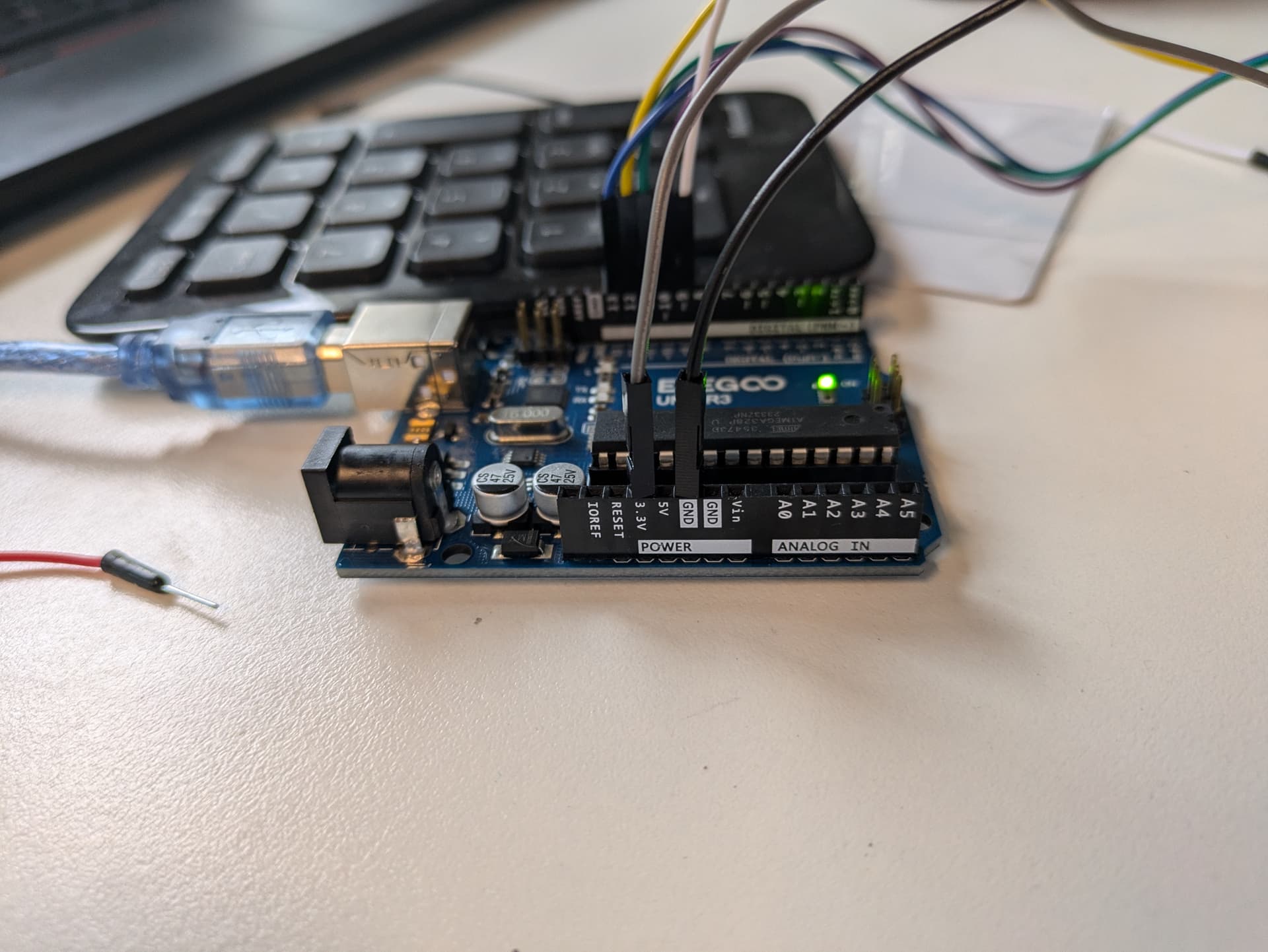
Ive been having trouble trying to get anything out of an RC522 RFID reader with my new Elegoo Uno R3.
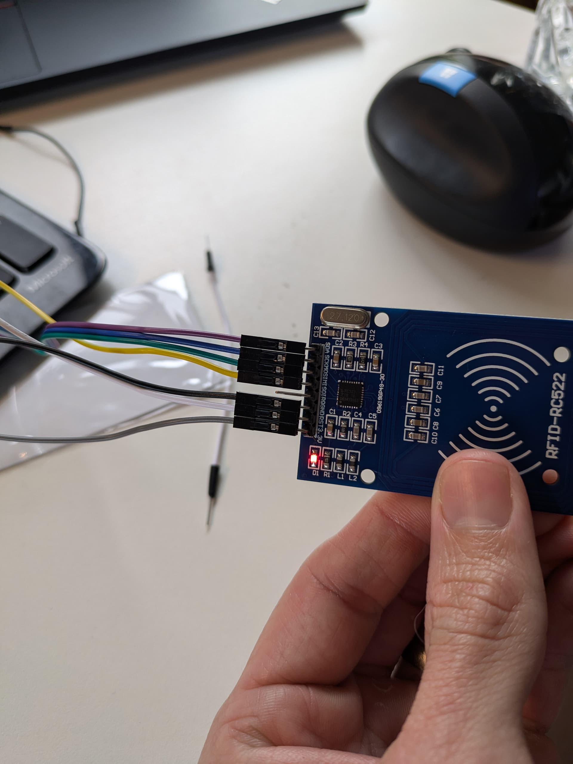
I have tried 3 different RC522 boards, all with the same issue. 1 came pre-soldered, I have attached a photo of one of the ones that I soldered so I don't believe that is an issue.
Other little tester projects worked ok, lighting up LEDs, buzzers & wiring up an accelerometer so I don't think that the Elegoo itself is broken.
I also saw a few posts about the RC522 only accepting 3.3v and the Digital pins being 5v so tried an HW221 converter but still with no luck. (The Elegoo support still maintain that this isn't required saying that
The VCC pin can only connect 3.3V but its IO is compatible with 5V
I'm using the Dumpinfo code
/*
 * --------------------------------------------------------------------------------------------------------------------
 * Example sketch/program showing how to read data from a PICC to serial.
 * --------------------------------------------------------------------------------------------------------------------
 * This is a MFRC522 library example; for further details and other examples see: https://github.com/miguelbalboa/rfid
 *
 * Example sketch/program showing how to read data from a PICC (that is: a RFID Tag or Card) using a MFRC522 based RFID
 * Reader on the Arduino SPI interface.
 *
 * When the Arduino and the MFRC522 module are connected (see the pin layout below), load this sketch into Arduino IDE
 * then verify/compile and upload it. To see the output: use Tools, Serial Monitor of the IDE (hit Ctrl+Shft+M). When
 * you present a PICC (that is: a RFID Tag or Card) at reading distance of the MFRC522 Reader/PCD, the serial output
 * will show the ID/UID, type and any data blocks it can read. Note: you may see "Timeout in communication" messages
 * when removing the PICC from reading distance too early.
 *
 * If your reader supports it, this sketch/program will read all the PICCs presented (that is: multiple tag reading).
 * So if you stack two or more PICCs on top of each other and present them to the reader, it will first output all
 * details of the first and then the next PICC. Note that this may take some time as all data blocks are dumped, so
 * keep the PICCs at reading distance until complete.
 *
 * @license Released into the public domain.
 *
 * Typical pin layout used:
 * -----------------------------------------------------------------------------------------
 *             MFRC522      Arduino       Arduino   Arduino    Arduino          Arduino
 *             Reader/PCD   Uno/101       Mega      Nano v3    Leonardo/Micro   Pro Micro
 * Signal      Pin          Pin           Pin       Pin        Pin              Pin
 * -----------------------------------------------------------------------------------------
 * RST/Reset   RST          9             5         D9         RESET/ICSP-5     RST
 * SPI SS      SDA(SS)      10            53        D10        10               10
 * SPI MOSI    MOSI         11 / ICSP-4   51        D11        ICSP-4           16
 * SPI MISO    MISO         12 / ICSP-1   50        D12        ICSP-1           14
 * SPI SCK     SCK          13 / ICSP-3   52        D13        ICSP-3           15
 *
 * More pin layouts for other boards can be found here: https://github.com/miguelbalboa/rfid#pin-layout
 */

#include <SPI.h>
#include <MFRC522.h>

#define RST_PIN         9          // Configurable, see typical pin layout above
#define SS_PIN          10         // Configurable, see typical pin layout above

MFRC522 mfrc522(SS_PIN, RST_PIN);  // Create MFRC522 instance

void setup() {
	Serial.begin(9600);		// Initialize serial communications with the PC
	while (!Serial);		// Do nothing if no serial port is opened (added for Arduinos based on ATMEGA32U4)
	SPI.begin();			// Init SPI bus
	mfrc522.PCD_Init();		// Init MFRC522
	delay(4);				// Optional delay. Some board do need more time after init to be ready, see Readme
	mfrc522.PCD_DumpVersionToSerial();	// Show details of PCD - MFRC522 Card Reader details
	Serial.println(F("Scan PICC to see UID, SAK, type, and data blocks..."));
}

void loop() {
	// Reset the loop if no new card present on the sensor/reader. This saves the entire process when idle.
	if ( ! mfrc522.PICC_IsNewCardPresent()) {
		return;
	}

	// Select one of the cards
	if ( ! mfrc522.PICC_ReadCardSerial()) {
		return;
	}

	// Dump debug info about the card; PICC_HaltA() is automatically called
	mfrc522.PICC_DumpToSerial(&(mfrc522.uid));
}
The Uno is a 5V device. So its Voh is close to 5V. The MRFC522 is a 3.3V device. Its maximum Vih is 3.8V. Connecting the Uno's outputs directly to the MRFC522's inputs will eventually damage the MRFC522. Sometimes you get unlucky on the very first time out, and that may very well be what has happened to you.
I'm aware that there are many places on the web that say "oh, it's perfectly safe to do this", but I tend to believe the datasheet when it says that 0.5V over the supply voltage, or 3.8V, is the limit. But don't take my word for it: feel free to peruse the datasheet yourself and come to your own conclusions.
To safely operate the MFRC522 with a 5V board, at a minimum you need voltage dividers on SCK, MOSI and RST to bring the high level signal down to 3.3V. I prefer to use active level conversion. You can do that with little more than a 74AHC125. The wiring isn't onerous. I also prefer to use a discrete 3.3V regulator rather than rely on the limited current capacity of the 3.3V output on some Uno clones.
Ive tried redoing it all with the logic level converter ( TXS0108E 8-Channel Bi-Directional Logic Level Converter Module for I2C/SPI - 1.2-3.6V & 1.65-5.5V) Amazon link for more specs
But I still get the same issue, is the wiring on the converter ok? Seems to be plenty of guides on other components but not this one so I'm not as sure on it...
The error I get when using the Dumpinfo.ino is
15:12:33.612 -> Firmware Version: 0x0 = (unknown)
15:12:33.647 -> WARNING: Communication failure, is the MFRC522 properly connected?
15:12:33.746 -> Scan PICC to see UID, SAK, type, and data blocks...
Should this work? Hoping to at least get this going with the parts that I have, it looks like the 74AHC125 is a fortnight away on delivery to me in Australia!
I've never tried a bidirectional level shifter for this case. I'll have to ponder that.
If the AHC125 is hard to find, an HC4050 would also fit the bill.
And for a "it'll probably work and you may have the parts on hand" solution, a resistor voltage divider is worth trying. 1.2K on top and 2.2K on bottom does 5V -> 3.23V.
Ive got nowhere, even trying the resistors so have just purchased another Uno R3 board to see if that is somehow the issue.
Failing that, I think the issue might be something on my computer/software , despite it all seeming to be working correctly, thats just the next thing involved
That circuit is not correct. It seems to be feeding the 5V reset pin directly into the RST pin of the RC522. It also does not feed the RC522 output signals correctly. That is it does not boost them up to 5V. That applies to the MISO pin in your circuit.
This is how to wire up a RC522 using just resistors.
Having said that, as noted before, you might have already damaged the RFID reader already.
Most RFID reader boards are not setup to use the I2C lines or the SPI ones for that matter. So do you know if yours is any different from the normal ones you get on eBay?
We do get a lot of problems from Elegoo users however, but I am not sure if this is the users or something about the board.
I responded to this Topic but can't seem to find it anywhere. I had the same problem with my Elegoo UNO R3 and the RC522. I was able to get it to work by connecting the 3.3V Pin on the RC522 to the Vin Pin on the UNO. I was using USB to power my UNO to Vin was read at 4.5V. This was the only way to get my RC522 to finally read my RFID cards. I know connecting the RC522 to anything over 3.3V can damage the sensor, but at least I got it to work. After some troubleshooting I believe the PROBLEM is the RC522 Sensor module that comes WITH the ELEGOO kit. I've used other RC522's with my Elegoo UNO and have no problem with them connected to 3.3V. So its not the Elegoo UNO folks! its THEIR RC522 that comes with the kit that has problems.
This fixed the problem I was having with the RC522 in my elegoo kit. One difference is that the elegoo MF-RC522_RFID program expects reset on Pin 9 not Pin 5(#define RST_PIN 9). I used 330 Ohm resistors(rather than 300) as that is what comes with the kit.
I also added a function call to the setup function to show the version as the example program does not include this.
mfrc522.PCD_DumpVersionToSerial();
For me when working this outputs
Firmware Version: 0x18 = (unknown)
When not working I got
Firmware Version: 0x0 = (unknown)
WARNING: Communication failure, is the MFRC522 properly connected?
I guess I was lucky the 5v signals did not break the chip clearly the elegoo instructions need an update.
Thanks a lot for the post, nice to get this working.