I've been working with an ATtiny85 for a while now have it programmed and running code fine on a breadboard. So I thought it was time to take this project portable. But when I make the same connections on a homemade board the ATtiny spit out the code improperly, if at all.
I've made two separate protoboards tinkering with the connections but the ATtiny still doesn't execute the commands properly.
To start the breadboard was comprised of a ATtiny85, trinket backpack and a USB micro breakout. Wiring the 5V supply from the USB to the backpack 5V, GND to GND. Therefore the backpack will charge when the USB is plugged in. I wired Vbat from the backpack to Vin on the 85. I then ran a LED from pin 1 of the 85 to GND. Pin 2 has a tact button attached. When the button is pressed and held the light goes on. Secondary presses result in different light functions. Holding the button turns it off.
This LED and tact button will work when the USB is plugged in and the battery is charging and when the USB is disconnected.
I then built a proto-board in eagle mimicking these connections *note that the Microcontroller is lifted from the breakoutboard in which it was programmed and tested and placed on the proto-board. The pins aren't heated more then a few seconds with little solder between them as I intended to transfer them.
The first board I made the controller partially worked. When plugged in the 85 will run though its functions but when detached from the USB the light will blink several times then remain on until the button is realest. On the second board I edited the eagle file a bit making the connection from the 85's Vin and Vbat more prominent as the first time the capacitor near Vin on the 85 connected before meeting Vbat. However this circuit doesn't not work at all. The microcontroller shows no response when the button is pushed or held, whether plugged in or not.
Attached are pictures of the eagle board, schematic and breadboard.
Thanks,
-Jesse
p.s. Is there a better way to mount the USB micro or a specific model that works best with with 1.5mm PCB or DIY projects? I must have ripped out a Dozen of these from other test boards? :o :o
Where is the 0.1uf capacitor between Vcc and Gnd, located right next to the chip? Is it C2? If so, where's the 4.7uf cap on VBat as spec'ed in the datasheet for the MCP73831?
I suspect that you have omitted it, which would explain why nothing works! It is required for proper operation, and the tiny85's are very sensitive to that IME (which is probably better than atmega's which often appear to work without the decoupling cap, and then when you're confident the design is okay - then you find something that breaks it, and you tear your hair out, because you've proven the hardware design right?). I've had to respin boards because I put the cap too far away. Try dead-bugging a 0.1uf cap ontop of the chip.
C2 initially ran directly into VCC then to the positive terminal of the battery. I edited it to go to the battery then VCC to make it more like th breadboard. But it doesn't work at all now.
No, you need a third capacitor, 0.1uf between Vcc and Gnd, right next to the tiny85.
The MCP73831 datasheet says it needs the two 4.7uf ones.
The tiny85 datasheet says it needs a 0.1uf one.
Why is it so hard to convince you to do what the datasheets tell you to?
I suggested (back in my first reply!) that you tack a 0.1uf through-hole cap ontop of the tiny85 between Vcc and Gnd on one of your current boards. Try that.
You need the decoupling caps (0.1uf is usually the value - I've used a few parts that spec 0.01uf for one of them) because digital IC's switch very quickly, so the current they're drawing can change very quickly, such that the inductance of the traces supplying power causes a very brief power glitch. So you put a small cap right next to it. I've never been able to wrap my head around why you need smaller caps to filter higher frequencies (an engineer with 40+ years of experience has tried to explain it to me several times, showed me the graphs, and I can accept them, but I don't understand how they were created. Apparently, in really high end designs, they often put multiple decoupling caps of different values in parallel).
Haha I couldn't fine the place on the datasheet where it suggests using a .1uf cap.
I just gave it a shot on both of the protoboards. Nothing, same reaction the first board blinks a few times then remains on till the button is released and the seconds does nothing at all.
As far as smaller caps for higher frequency is it cause they become full and drain faster then a larger one would? Resulting in a higher frequency of occurrences.
Okay, now that we've gotten that out of the way we can proceed to actually debugging this.
I recommend not debugging anything that doesn't have decoupling caps - you can see so many kinds of weird behavior.
What you saw is the sort of behavior you often see from improperly decoupled designs - okay it sorta works... then it hangs, and not all chips in the batch behave the same way, and the person debugging it starts tearing their hair out.
Also, can you post the code they're running? What speed are you running the t85 at? If you're running it off the PLL clock, switch back to 8mhz.
Can you post a pic of the assembled boards? Are these boards being etched at home, or made by a board house? The way you talk in original post, it sounds like they're home-made?
You want to put an ISP header on the board if you can to reprogram them in place, and so you don't have to desolder the programmed chip.
And, regarding your question about those micro-usb connectors, the ones you're using are already the good kind - the bad ones don't have the through-holes. I have been generally disappointed in microUSB connectors - they're designed to have a case around them that keeps them from getting ripped off, I think.
#include<avr/interrupt.h>   // These are sets of 'library' functions needed
#include<avr/sleep.h>

const int switchPin = 2;
const int statusLED = 1;

uint8_t onOff;

volatile uint8_t buttonPushCounter = 0;
volatile uint32_t pressStart = 0;
volatile uint32_t pressEnd = 0;

void init_interrupt() {     // A function to set up the button press
  GIMSK|=_BV(PCIE);         // interrupt. It fires on any change on the pin
  PCMSK|=_BV(PCINT2);       // so on press or release of the button.
  sei();
} // end of init_interrupt

ISR(PCINT0_vect) {                      // This is the function the interrupt triggers
  if(digitalRead(switchPin) == LOW) {   // low will indicate the button press
    //buttonPushCounter += 1;           // increment the button press counter
    pressStart = millis();              // start/enable a 'soft' timer
  }
  else {                                // high indicates release
    buttonPushCounter += 1;             // or increment on release (better I think)
    pressEnd = millis();                //
  }                                     // Plus it wakes the trinket up from sleep of course
} //end of ISR


void setup() {
  pinMode(switchPin, INPUT_PULLUP);
  pinMode(statusLED, OUTPUT);
  onOff = HIGH;
  init_interrupt();             // set up the button interrupt

  //Flash quick sequence so we know setup has started i.e. power applied
  for(int k=0;k<10;k=k+1){
    if(k%2==0){
      digitalWrite(statusLED,HIGH);
    }
    else{
      digitalWrite(statusLED,LOW);
    }
    delay(250);
  } // end of flashing routine
} //  end of setup

void loop() {
  if(pressEnd) {                          // Button press released and can be measured
    if((pressEnd - pressStart) > 1000) {  // if it was pressed longer than a second
      onOff = !onOff;                     // toggle device on or off
    }
    pressStart = 0;               // disable the 'soft' timer (see line 82)
    pressEnd = 0;
  }
  if(onOff) {                             // if switched on, run the switch statement
    switch(buttonPushCounter)
    {
      case 1:
        digitalWrite(statusLED,HIGH);       // full LED on 1st press
        break;
      case 2:
        analogWrite(statusLED,127);         // next press set the led to half
        break;
      case 3:
        analogWrite(statusLED,85);          // quarter
        break;
      case 4:
        analogWrite(statusLED,45);          // and dimmer
        break;
      case 5:
        analogWrite(statusLED,15);          // dimmest
        break;
      case 6:
      digitalWrite(statusLED,HIGH);
      delay(50);
      digitalWrite(statusLED,LOW);
      delay(50);
      break;
      default:
        buttonPushCounter = 1;              // another press or any other unforeseen roll over counter
        break;
    } // end of switch
  } // end of on functionality
  else {                                     // if switched off
    if(!pressStart) {                        // ...and not currently timing a button
      digitalWrite(statusLED,LOW);           // lights out
      buttonPushCounter = 0;                 // counter back to 0
      set_sleep_mode(SLEEP_MODE_PWR_DOWN);   // go to sleep
      sleep_enable();
      sleep_cpu();

      sleep_disable();
    }
  } // end of off functionality
}
It works pretty well on the breadboard, every now and again it'll skip one of the light commands or turn off before its suppose to. I'd like to fix that but it works pretty well at the time being.
Funny thing about the chips are some will only program and run at 8mhz while others will only accept code at 1mhz.
I wasn't sure how to put an ISP header or exactly what it was either, this seemed like the most practical approach to getting it done otherwise.
All home etching.
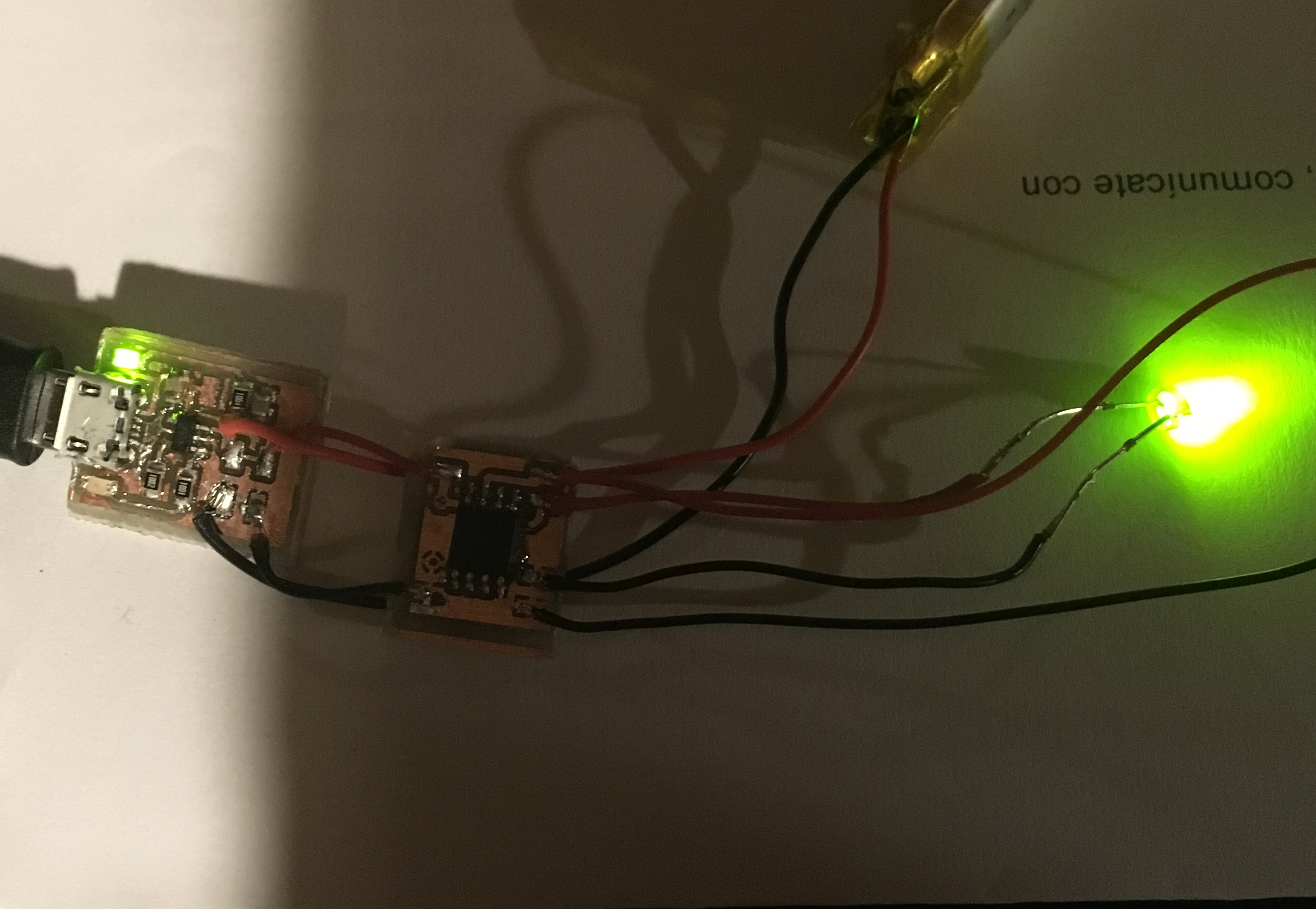
The picture is of the latest board, which I believe is running at 8mhz. The first board that blinks is probably running at 1mhz. *picture taken before soldering the cap.
My fingers holding the USB down. I was thinking about trying to use some solder past on the next board and throw it in a skillet. Before soldering anything else just in case I accidentally fry the ic that way.
Reason some will only program at 1mhz is probably due to the lack of decoupling caps.
ISP header is the 2x3 pin header that's widely used for programming via SPI (ex, it's what the ubiquitous, $3 USBAsp programmers use). It breaks out all the pins uses for ISP/SPI programming in one convenient connector, and eliminates problems from mis-connected wires when programming.
Any chip without a 0.1uf cap between Vcc and Gnd right on the chip should not be trusted to work or not work.
I know the 85 can be set to use an external crystal and so come that way from secondary sources but from what I understand if you can send it code well setting it to one of the internal mhz settings then a crystal is not needed. Is this what your asking Cross Roads?
Thanks Drazzy, I'm gonna cut a board drilled for the 0.1uf cap. Hopefully that will do the trick. I retested the breadboard setup today using a MCP73831 breakout I made instead of the trinket backpack. It works, Its a little finicky sometimes. But seems to work better with the 0.1uf cap on it.
With the acception of two issues the board seems to be working. The ATtiny runs code. However it never fully turns the light off on the prolonged button press. It remains very dim. I didn't place a resistor on the LED could this be the reason?
Second issue is the charger indication LED's never go on when plugged in. I'm assuming it's poor connection?
*Noting I used solder paste and a skillet to mount the USB, the connections seem stronger.
Second board of the day removed the throughhole wire holes and just left pads. Thought the connection might have been getting interrupted from top to bottom. Now the entire circuit sits on the top.
The ATtiny was removed from the last board and placed on this one. Program doesn't seem to work as well, I tested it before putting it on and it worked just fin.
What it does now is goes bright until button is release then dims a bit. If pressed consecutively it will blink slowly about 6 times before remaining steady. Sometimes if lucky it'll run the code a few times through after that. Otherwise it just repeats the blinking every time the button is pressed.
It go extremely dim after the prolonged press every time.
The indication charge lights of the MCP73831 still doesn't seem to work at all.
Is there a reason why the circuit functions so much better on the breadboard then on the Porto board?
Yes, obviously there's a reason! I'm not exactly certain what it is, though... Do you have an oscilloscope? There's a reason for everything; the laws of physics are not changing here - but I'm struggling to think of further debugging steps other than putting the scope on it and systematically monitoring every line on breadboard vs assembled board.
How are you moving the chip over? Are you sure you're not damaging it in that process? I mean, you should be able to do that, but I can't see your technique, so I don't know if you might be abusing it in some way (I am not worried about heat so much as physically damaging the package - if you cracked it, that would probably result in intermittent behavior, for example)
"With logic circuits and micro controllers, leaving a floating input can render your circuit useless. Inputs should be grounded or connected to V+ through a 4.7 to 10K ohm resistor. Otherwise the input can act as an antenna and pick up spurious signals from house hold AC or other sources."
Should I GND all other pins?
I'm pretty gentle with the removal I take a very thin pair of hooked tweasers and slide it under the legs, heat from the side and slide it along. I go around the whole chip to insure I don't pull a leg off.
Yeah I have an oscilloscope I'll run some tests. First I gotta make another tiny breakout.
AVR's are fine with floating inputs. I think the manufacturer recommendation is to enable the pullup on unused pins to keep them in a known state, but I've never heard of anyone having problems other that slightly increased power consumption from having floating inputs on any AVR microcontroller.
On the first board I placed the ATtiny on the bottom. On a hunch that maybe there was some interference between the 85 and MCP. No go the ATtiny would only run commands when the USB was plugged in and it would affect the green done LED on the of the MCP with each press.
The second board I devided the two main components (ATtiny and MCP) on two to separate boards and used jumpers to connect the two. Although more complicated then I'd like it to be the current combination actually works. Any thoughts on why this might be? Any possible way of consolidating these chips onto a single board while maintaining proper functionality?