Motor Driver (with reverse polarity protection) Not working after reverse connection to 12V battery

Hi everyone, this is my first post, so I will try to be as detailed as possible. If you need more information, please ask, and I will do my best to respond ASAP.

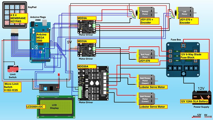
Here is my situation: I have a tennis ball machine that I built using an Arduino Mega and a bunch of other components, as shown in the picture. Please note that the picture is slightly incorrect. The fuse box has two 2A fuses and one 35A fuse, unlike the picture, which shows 5A, 2A and 35A fuses.

I use two Cytron MDD3A motor drivers to drive three 12V gear motors with a stall current of 1A each. I also use an MDD20A to drive two 12V motors that can do 6000 RPM and draw a larger current. Unfortunately, I don't have specs on that motor, but when I tested it with a 20A fuse going into the driver, it blew the fuse. It works fine with a 35A fuse. That is 35A total current going to the driver, and the driver can handle 20A per channel, so I am under the maximum continuous current the driver can handle.

Now, like an idiot, I connected the battery to the fuse box in reverse. Rookie mistake, but stuff happens, right? I immediately noticed smoke coming from the fuse box and disconnected the battery as quickly as I could to prevent any damage (instinct, I guess).

Upon checking, I noticed the 35A fuse was blown. The two 2A fuses were still intact. But when I replaced the 35A fuse, the circuit was not working correctly. The MDD20A was sending power to the motors as soon as I connected the power, which is not how it usually behaves. It only sends power to the motors if I press one of the onboard buttons or if the Arduino sends the signal.

I also noticed that the two MDD3As were not sending any power to the worm gear motors when I tested them using the onboard buttons. In case you are wondering what I am referring to when I say "onboard buttons," these are forward and reverse buttons on the motor driver that Cytron provides for quick testing. Press them, and the driver sends power to the motor without any signal from the Arduino.

Okay, I need to ask the question at some point, so here it goes. I am still debugging the circuit and may have other questions that I may post, but for now, my question is: why did my MDD3A drivers get fried even with reverse polarity protection? The larger MDD20A works fine, but the smaller MDD3As seem to have given up the ghost. I should add that when I tested the voltage at the output of the MDD3A, it shows 5V when no load is connected, but when a load is connected, it goes down to 0.xx V, which is practically 0.

Luckily, I used the 5V output from the MDD3A to drive my Arduino Mega, and that seems to have survived the mishap, as did all the other motors and input components. Basically, the MDD3As seem to have sacrificed themselves to protect the other components they provide power to.

This has turned out to be more of a story than a pointed question, and I apologize for that. I am not an electronics expert and rely on a lot of information on the internet to get by. Thanks for your valuable input.
Quick update - just tested MDD20A for PWM and it's not working. The onboard buttons seem to work but I cant control motor via the PWM or DIR pins.

Hi, @jaa-2024
Welcome to the forum.

We need to see your code and schematic of your circuit.

Thanks... Tom.... :smiley: :+1: :coffee: :australia:

Thanks Tom, I thought I had uploaded the circuit diagram. I dont have a schematic but do have this that I drew using good ol powerpoint. Hope this helps. As for code, I simply tested using PWM control code for cytron motor driver and that didn't work.

I just wanted to call out that the mistake I did was to connect the fuse to battery in reverse polarity. And the 35A fuse blew of instantaneously.

My arduino program is over 3000 lines and it only executes motor driver control when I press start. Otherwise it just waits for user input albeit display useful info on the LCD display so it does execute some commands but nothing to do with motors.

Another update, I tested Arduino with L298N controller and it worked just fine driving the gear motors. So Arduino seems to be working as expected.

I guess what I need to know is why did the motor drivers from cytron get damaged due to reverse polarity despite claiming protection from it. Is my circuit diagram missing something basic?

Hi, @jaa-2024

Can you please post a copy of your circuit, a picture of a hand drawn circuit in jpg, png?
Hand drawn and photographed is perfectly acceptable.
Please include ALL hardware, power supplies, component names and pin labels.

We need to see pin names and numbers and pen(cil) and you will find paper is a lot easier to layout.

Have you got simple code to simply test the Cytron drivers?

Tom.. :grinning: :+1: :coffee: :australia:

Nothing wrong with your diagram.
I would expect that the 20A would be damaged but have no explanation why the 3As failed. However who knows what kind of voltage transients occured when the 35A fuse blew and if the damaged 20A may have sent unexpected currents through all the ground connections.

To be fair, not just rookies. I remember seeing a coil of smoke gently rising from the back of some test equipment, shortly after the guy sat in front of it turned it on. He was using a PSU "found in the lab" which was the wrong polarity...

Sadly, the claimed features for a product don't always work as intended, and sometime the product doesn't even have the feature. Without a schematic, or forensic analysis, I can't say exactly what happened here.

It appears only the MDD3A is claimed to have reverse polarity protection. I guess you could try getting a refund from the seller.

Either way it is a good learning experience, and thorough checking is your friend.

The reverse polarity protection could have been a shunt diode across the power input terminals, reverse biased with correct protection.
Might have been worth putting in a fuse, especially if using a high capacity battery.

Tom.... :smiley: :+1: :coffee: :australia:

Thanks Jim, and sorry for not responding earlier.

I'm glad you see my circuit not having obvious flaws. The seller who is an authorised reseller for cytron has offered to replace the 3As under warranty but the 20A is not covered and rightly so.

I am trying to implement some protection against reverse polarity by getting a connector in place to address the human error.

Do you have any other ideas I can employ to improve this circuit in addition to the fuse? I am thinking of things like ideal diode or Schottky diode but I am not sure if I need to add them before or after the fuse. If I have to add that after the fuse, I need to add one for each of the driver but I can add just one if I put it before the fuse but I am not sure which is the better way to do that.

Any thoughts?

THanks Bob, yes the seller has agreed to replace the MDD3As. But not the MDD20A as it's not claiming to have that protection. But bummed as to why that is the case but I guess it's to save costs probably but I am not sure if that is why the larger more expensive driver doesn't have that protection.

THanks Tom,

I intend to use something like that to ensure my circuit is projected. I do have a fuse box that has differing fuses for the 3 drivers. MDD3A have a 2A fuse each and MDD20A has a 35 A fuse. Would you receoment having a shunt diode before or after the fuse and does it make a difference if it's before or after?

Also, given my total load is around 40A (35+2+2), can you recommend a suitable component? Sorry to ask for specifics but I am new and dont know much about it. Thanks for your inputs.

After the fuse, so reverse polarity will blow the fuse.
Put the diode at the motor driver power terminals.

Tom.... :smiley: :+1: :coffee: :australia:

1 Like

Here's a diode with 60A max forward current and 45V reverse protection. It should suit your needs. Only a few bucks too. Hope this helps.

https://www.mouser.com/ProductDetail/Diodes-Incorporated/SBR60A45CT?qs=nSryOFbzj8LIOIQ%2F6BdIuA%3D%3D

1 Like

Tom.... :smiley: :+1: :coffee: :australia:

1 Like

The diode is going to get hot. With a Vf of 0.5V at 3x3A that would be 4.5W. If you can heatsink the diode then OK. One diode for each driver is only 0.5V x 3A = 1.5W
.
Personally I'd go with one diode for each driver.

2 Likes

Thanks everyone, I am learning so much abut this topic from your inputs, I dove deep into the subject after your inputs and found this chip from Pololu Ideal Diode Reverse Voltage Protector, 4-60V, 10A that offers reverse voltage protection. They have several others that offer differing Amp ratings.

Would that be suitable in this application?

My aim is to use the knowledge and expertise of companies like these that offer specific products to help address an issue or in this case human error.

Also, I am going to properly test my motors to know what is the initial current draw and the steady state current draw (no load) and the current draw when the motors throw a ball out.

I feel the initial current draw should not be more than 35A which is what the fuse was handling before and steady state should be well below 25A. If so I might (assuming you also think its not a bad idea) use a 25A board for the big motors which has a peak current rating of 60A and 10A board for the other two drivers.

Having said that, I am seriously thinking of having one 25A board before the fuse. The ideal diodes as per my reading and watching videos dont get hot as they use MOSFET instead of a DIODE.

What do you think about

  1. Using the above mentioned board from Polulu as reverse voltage protection
  2. Can I get away with having the board before the fuse that way I minimise the no. of such boards?

Your inputs are really appreciated, thanks

Ok, I think I got the answer to 2nd question, it makes sense to add the diode after the fuse. So I need to protect the 3 drivers with 3 ideal diode boards.

I guess the question is if the ideal diode is a good solution for my application. I am leaning towards a yes but keen to hear the experts views on it as well. Thanks

If you use the ideal diode, it costs more money and adds to the design complexity. If you can afford the extra heat that a diode may put off, you can go the cheaper and simpler route. It is really up to you and what you want from this design. How professional, or environmentally rugidized, or mass manufacturable does this thing have to be?

Basically, if it's a one-off project, get the ideal diode boards and spend a few minutes connecting everything together and it will work fine. If you plan to make many of these, get the regular diode and everything else and make your own circuit board.

I hope this helps!

Perfect! Thanks for that response . I will go down the ideal diode route as it's a one off project and I have the luxe of time and a few extra bucks is ok.