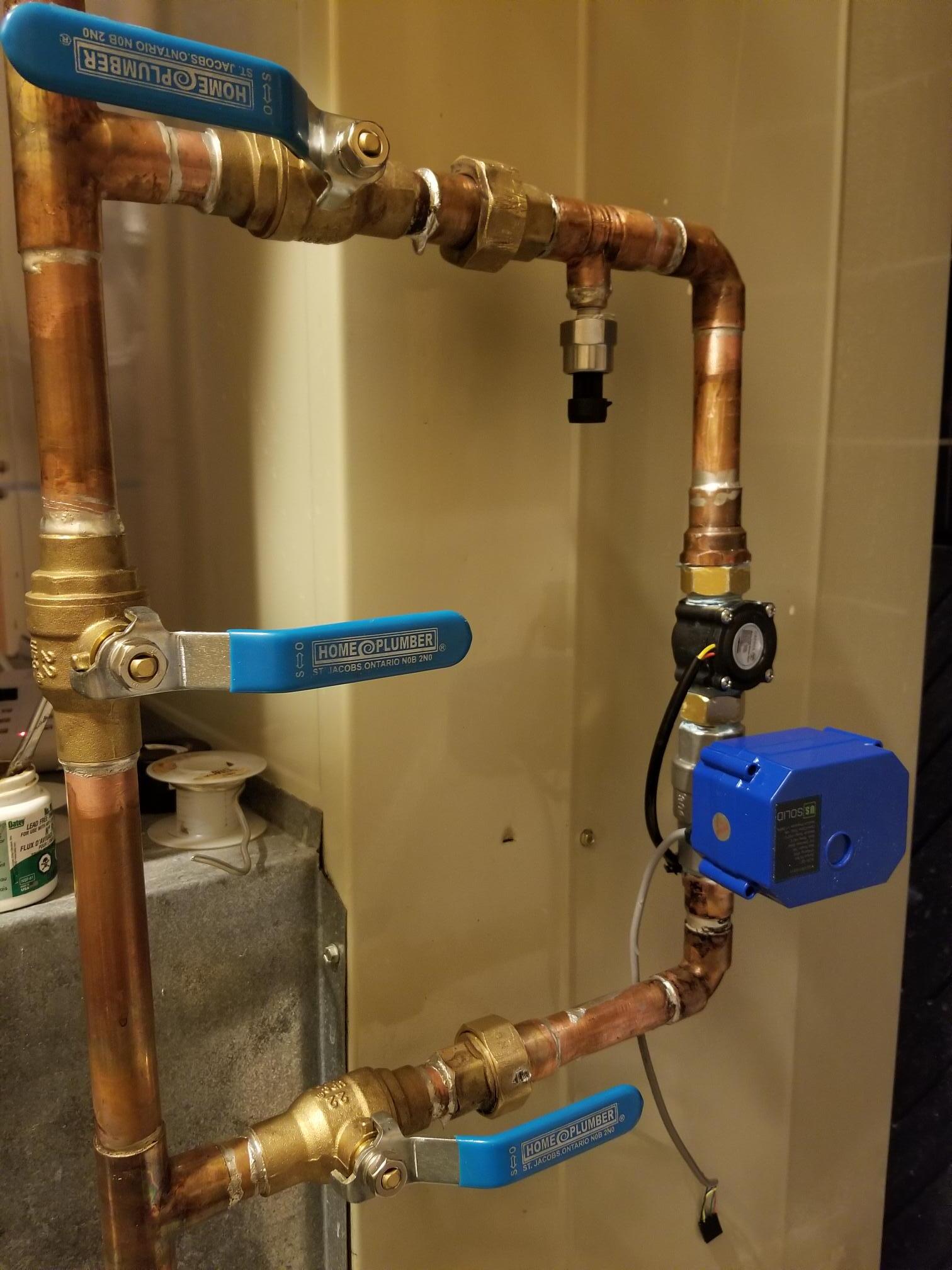
Good day everyone, I need some wiring advice, my project is to use this usSoild 3 wire motor valve Hardware: usSoild 3 wire motor valve
Nano 33 Iot
Mosfet IFR520
Push Button
What I want it to do: When the desired value is meet, nano sends a single to the gate to open the MOSFET, then this completes the path, and the valve closes and stays closed. Perfect, this is what I wanted to happen and it does.
Now that the valve is closed, I would go and investigate why it was closed, and once satisfied with that, I would reset the Nano controller and wanted to wire up a push-button to manually supply the power to reopen the valve,
this is where I'm confused about how to do this.
As this valve requires that the 12v positive that I'm using is supplied to both red wire (open) & blue wire (close)
and shares a common ground (yellow) to work for either one.
I understand how to hook up a momentary push button to supply 12v power to the red wire (open)
But where I'm really confused is, I need the ground wire (yellow) to complete the push-button circuit (open).
If I jumper the ground (yellow)over from the Drain to the ground, this completes the circuit, and the value just closes as then the circuit is complete to the close it.
I just don't understand how to wire this up with just one ground and tow 12v postive connections
Have a look at the video from your link ; it explains the connection to make .
IF it’s a AC/DC valve you should be able to connect + to the yellow and switch either of the other wires to 0v to open or close it .
If not you can use a P type FET to switch the positive supply to the two wires and connect the yellow to Ov
Note that the circuit you have is not going to work as the IRF520 is not logic-level, and is not a
good choice for a low voltage load anyway due to its very high on-resistance.
If you do move to p-channel FETS for high-side switching, and have a 12V supply, the FETs
don't need to be logic level, as the level-shifting circuit (typically a small NPN transistor) raises
the 5V to 12V for the FET.
But if you want to switch low-side with an n-FET like this, it must be logic-level, and whatever
FETs you choose aim for < 0.1 ohms on-resistance for handling loads of upto a couple of amps, and
< 0.01 ohms for upto 5A.
For low voltage circuitry don't pick a 100+V MOSFET, the other parameters will be poorer.
You need 2 P-channel MOSFETs and 2 NPN BJTs (2N3904) + bias resistors. Like the second "high side switch" schematic for each direction (open / close) here, I would make R1 680 Ohms though. https://www.gammon.com.au/motors
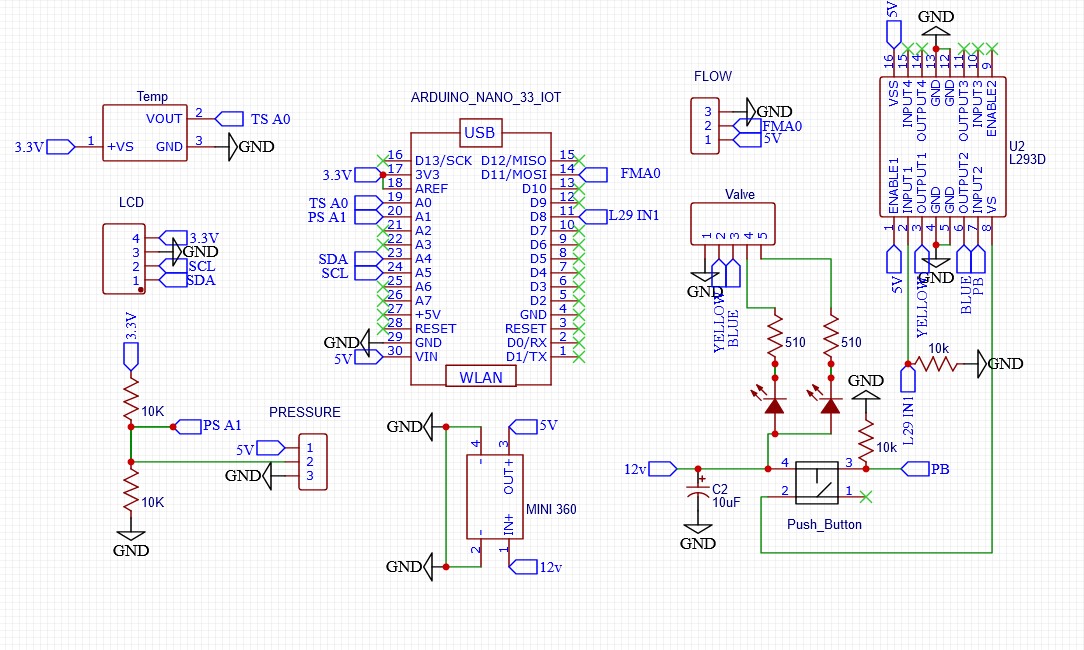
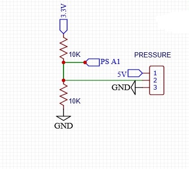
TomGeorte, thanks for pointing out my voltage divider, clearly it's wrong and has been corrected. Thank you for catching that. Pressure Sensor
JCA34A, you all have been very helpful and have steered me in the right direction, thank you. Those two extra wires are just for open/close LED's and it did not matter if I used them or not. As the end of the day, I have learned a lot from your help and others here. THANK YOU
[
JCA34F:
The schematic shows you are putting 12V on the L293s INPUT2 pin, better check that.
JCA34F, GREAT CATCH thank you, have corrected, this is the most advanced project I have done so far with Arduino. Been a great learning experience and appreciate the positive help I have received from you and others on this forum.