kleines Update:
habe heute am Code gesessen, jetzt läuft's 
/* based on LucidTronix 4 Digit sketch
 * modifyed by Ger@ld 1/2014
 * Daisy Chained Shift Registers
 * 6x 74HC595 connected to 7-Segment LED display
 * with DS3231 Real time clock chip
 * Tutorial at:
 * http://www.lucidtronix.com/tutorials/52
 * September 2013
 */
#include <Wire.h>
#include "RTClib.h"

RTC_DS1307 RTC;

int dataPin = 10;
int latchPin = 8;
int clockPin = 9;
int fotPin = 3;    // select the input pin for phototransistor; GND to E phototransistor C to input + 1M --> +5V
int dimPin = 6;    // select the pin to drive Output Enable from shift registers (pin 13)
int fotVal = 0;    // variable to store the value coming from the sensor

byte dec_digits[] = {0b10111111,0b00000110,0b11011011,0b01001111,0b11100110,0b01101101,0b11111101,0b00000111,0b11111111,0b01101111 };

void setup() {
  //set pins to output so you can control the shift register
  pinMode(latchPin, OUTPUT);
  pinMode(clockPin, OUTPUT);
  pinMode(dataPin, OUTPUT);
  pinMode(dimPin, OUTPUT);  // declare the Dim_Pin as an OUTPUT

  Wire.begin();
  RTC.begin();
  if (! RTC.isrunning()) {
    RTC.adjust(DateTime(__DATE__, __TIME__));
  }
}

void loop() {
  DateTime now = RTC.now();
  int thehour = now.hour();
  // switch between 24 hour clock and 12 hour clock
 // if (thehour > 12 ) thehour -= 12;
  int hour_tens = thehour / 10;
  int hour_ones = thehour % 10;
  int minute_tens = now.minute() / 10;
  int minute_ones = now.minute() % 10;
  int second_tens = now.second() / 10;
  int second_ones = now.second() % 10;

  digitalWrite(latchPin, LOW);
  shiftOut(dataPin, clockPin, MSBFIRST, dec_digits[second_ones]);
  shiftOut(dataPin, clockPin, MSBFIRST, dec_digits[second_tens]);
  shiftOut(dataPin, clockPin, MSBFIRST, dec_digits[minute_ones]);
  shiftOut(dataPin, clockPin, MSBFIRST, dec_digits[minute_tens]);
  shiftOut(dataPin, clockPin, MSBFIRST, dec_digits[hour_ones]);
  shiftOut(dataPin, clockPin, MSBFIRST, dec_digits[hour_tens]);
  //take the latch pin high so the LEDs will light up:
  digitalWrite(latchPin, HIGH);
  {
  fotVal = analogRead(fotPin);            // read the value from the sensor
  fotVal = map(fotVal, 0, 1023, 0, 254);  // scale it to use it with the LED - map to 254, cause 255 is complete off

  analogWrite(dimPin, fotVal);            // set brightness
 }
  // pause before next value:
  delay(100);
}
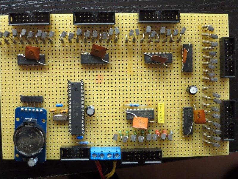
An Analog In 3 hängt ein Fototransistor. Emitter gegen Masse und Collektor am Eingang, Widerstand 1M vom Eingang gegen +5V. Digital Out 6 steuert die Pins 13 von den 595 Schieberegistern zum Dimmen per PWM.
fotVal = map(fotVal, 0, 1023, 0, 254); verhindert, das bei völliger Dunkelheit die Anzeige ebenfalls komplett abgeschaltet wird
Qh der 1-er Sekunden nutze ich, um den Doppelpunkt blinken zu lassen. Dazu habe ich im Arry alternierend immer die geraden Werte 1 gesetzt und die Ungeraden auf 0. Ist simpel und dirthy ]
Das RTC Modul habe ich steckbar gelassen. So kann ich es zum Stellen 2x im Jahr entnehmen und auf dem Breadboard stellen.
Na mal sehen, ich werde irgendwann mal ein Funkuhrmodul testen. Daliegen habe ich schon eins 
Ansosnsten, wenn es noch Fragen zum Aufbau oder Verbessereungen am Code gibt, nur zu 
Gruß Gerald
LED_6_digClock.hex (14.4 KB)