Member LarryD turned me on to these little displays from Sparkfun, little bubble display 4 7-segments displays.
He uses them in a pulse counter box he makes.
Taking 2 and mating them with a MAX7219 from Tayda electronics, and a couple parts makes up this little board.
I bought material for 50 cards, LarryD is buying 30 35 already!
So 2015 are available, $12.85 each plus shipping; I think a kit in padded envelope shouldn't be too much, will find out next week.
If there's interest, I can get more until Sparkrun runs out of displays.
The 10uF can be mounted flatter, or on the back.
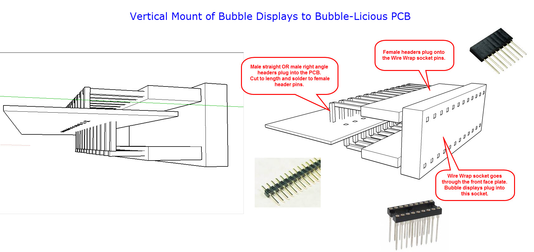
The holes for the display have double rows to accommodate a right angle socket, 2 of mouser 575-2994331211,
and put the display at right angle to mount the board behind a panel. Pricey tho, $7.61 for a pair when purchased in 10-lots.
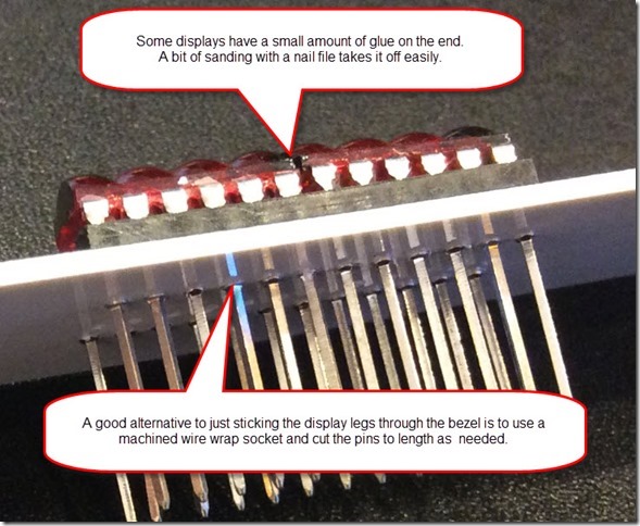
Wirewrap socket can be bent up also, I'll leave that to the user.
"Description: This is the HP QDSP-6064 bubble display, a tiny, 4-digit, 7-segment numerical indicator. This little guy is perfect if you need some user feedback from your system, but don’t want to fiddle with LCDs or other display options. The Bubble Display comes in an easy-to-use 12-pin DIP package and can be used in breadboards, protoboards, or PCBs.
These bubble displays have a peak forward current per segment of 5mA at a peak forward voltage of 2V. Thanks to a neat magnification technique used by the QDSP-6064 (giving it the “bubble” name), the luminosity is intensified making lower power consumption possible."
I'm running with a 10K Iset resistor and intensity set to 6, seems to work pretty well.
//Bubblelicious  test
#include <SPI.h>

byte ssPin = 10;

byte fontArray[] = {
  // dp-a-b-c-d-e-f-g
  0b01111110, // 0
  0b00110000, // 1
  0b01101101, // 2
  0b01111001, // 3
  0b00110011, // 4
  0b01101101, // 5
  0b01101111, // 6
  0b01110000, // 7
  0b01111111, // 8
  0b01111011, // 9
  0b01110111, // 10 A
  0b00111101, // 11 d
  0b01001111, // 12 E
  0b00110111, // 13 H
  0b00010000, // 14 i
  0b00001110, // 15 L
  0b00010101, // 16 n
  0b00000101, // 17 r
  0b00011100, // 18 u
  0b00011101, // 19 o
  0b00000000, // 20 blank
};

byte messageArray[] = {
  13,12,15,15, 0,20, 4,20, // HELLO 4
  10,17,11,18,14,16,19,20, // Arduino
};


byte Noop = 0x00;
byte decodeReg = 0x09;
byte normalReg = 0x0c;
byte displayReg = 0x0f;
byte scanReg = 0x0b;
byte intensityReg = 0x0a;

byte digits[] = {
0x01, 0x02, 0x03, 0x04, 0x05, 0x06, 0x07, 0x08,};

byte x;

void setup(){
  SPI.begin();
  digitalWrite (ssPin, LOW);
  SPI.transfer (intensityReg);
  SPI.transfer (0x06);
  digitalWrite (ssPin, HIGH);

  digitalWrite (ssPin, LOW);
  SPI.transfer (decodeReg);
  SPI.transfer (0x00); // no decode for all digits
  digitalWrite (ssPin, HIGH);

  digitalWrite (ssPin, LOW);
  SPI.transfer (scanReg);
  SPI.transfer (0x07); // all 7 digits
  digitalWrite (ssPin, HIGH);

  digitalWrite (ssPin, LOW);
  SPI.transfer (displayReg);
  SPI.transfer (0x00); // normal operation
  digitalWrite (ssPin, HIGH);

    digitalWrite (ssPin, LOW);
  SPI.transfer (normalReg);
  SPI.transfer (0x01); // normal mode
  digitalWrite (ssPin, HIGH);
}
void loop(){
  for (x=0; x<8; x=x+1){
    digitalWrite (ssPin, LOW);
    SPI.transfer(digits[x]);
    //SPI.transfer (0x01);
    SPI.transfer (fontArray[messageArray[x]]);
    digitalWrite (ssPin, HIGH);
  }
  delay (750);
  for (x=0; x<8; x=x+1){
    digitalWrite (ssPin, LOW);
    SPI.transfer(digits[x]);
    //SPI.transfer(0x00);
    SPI.transfer (fontArray[messageArray[x+8]]);
    digitalWrite (ssPin, HIGH);
  }
  delay (750);
}