hello guys, I'm working on a vehicle construction project and I'm using some sensors to read data, such as speed sensors, emperaura, rotation and others.
My question is how would I show the data on my nextion display, well I already have the visual interface of the display created but I can't update the data from my sensors on the display.
I created a separate code just to try to change the values on the display but I still couldn't
Thank you for your code and HMI file. I'm not seeing the schematic I asked for. Please supply a schematic. If you don't know how to draw one see How to make a schematic you can post.. I have not verified your wiring from the photos and will not do so until you post a schematic.
In your code you are trying to send data to things that do not exist on the display, specifically:
n0.val,
n1.val
n2.val
You are also sending the data every time around the loop function without any interval in between each send. I don't know how the Nextion will react to this but you need to slow the data down to only send when something changes and only send to things that exist on the display.
You should start with simple code that updates one thing on the display only, get that right before doing anything else.
Here is code that will send data to j1 making it increase and then decrease:
void setup() {
    Serial1.begin(9600);
}

void loop() {
    sendTestData();     // Calls the function sendTestData to send data to the Nextion
}

// Sends data to j1 to make it increase then decrease
void sendTestData() {
    static int8_t j1Val = 0;            // Value to send to J1
    const int8_t j1Max = 100;           // Maximum value for J1
    static uint32_t lastMillis;         // Saves Millis for the time interval for sending data
    uint32_t currentMillis = millis();  // Current value of Millis so it is only read once
    uint32_t updateInterval = 50;       // Interval between each update of j1
    static bool increase = true;        // Direction of J1

    if (currentMillis - lastMillis >= updateInterval) {     // Check to see if the interval has passed
        lastMillis = currentMillis;                         // Save Millis for next interval
        Serial1.print("j1.val=");                           // Tell the Nextion that the data is for j1.val
        Serial1.print(j1Val);                               // Send the value to j1
        Serial1.write(0xff);                                // Nextion end marker
        Serial1.write(0xff);
        Serial1.write(0xff);
        if (increase) {                                     // j1 increasing
            ++j1Val;
            if (j1Val >= j1Max) {
                j1Val = j1Max;
                increase = false;
            }
        } else {                                            // j1 decreasing
            --j1Val;
            if (j1Val <= 0) {
                j1Val = 0;
                increase = true;
            }
        }
     }
}
I have tested this code on a Nano Every sending to a Nextion display with your HMI file on it, I confirm it works as expected. You should see j1 increase to maximum then go back down to minimum, then back up. If this does not happen then suspect a wiring problem.
Note that I created a separate function for the test code rather than jamming everything in to the loop function. Please do this in future, it makes testing so much easier. You should break your code into separate functions, each doing one thing. Look at my Nextion tutorial for more examples.
Note the use of millis for timing. If you are not familiar with the use of millis then study the blink without delay example in the IDE and the tutorial on this forum.
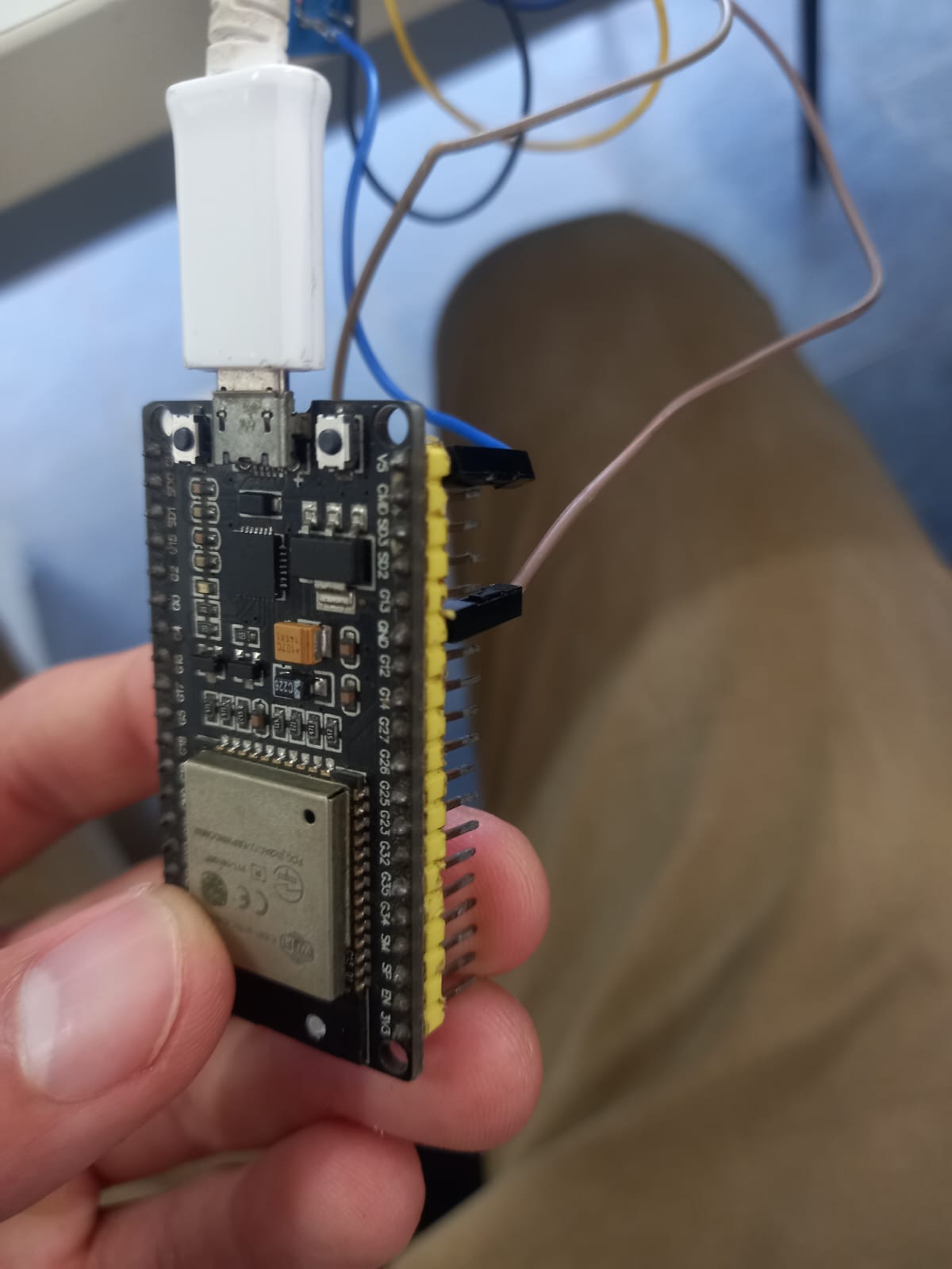
It concerns me that you say the board on the schematic is not the one you have, if that's the case how are you sure the Tx and Rx are where they are supposed to be? In the photos your board appears to have Tx0 as the third pin from the end, in the schematic is is the 4th pin from the end. Please create an accurate schematic.
The code I gave you works, I tried it. If it does not make j1 increase and decrease then you have something else wrong.
I cannot see in the photos where the wires are connected, the angle of the photos and the tangle of wires makes this impossible. If the display is lighting up then the red and black must be OK. Concentrate on the yellow wire for now and make sure it is connected between Tx0 and the Nextion. Do you have a multimeter to check continuity?
I am not familiar with the ESP32, I note that on the board the serial port is marked Tx0, whereas in code you are using Serial1, I don't know if this is correct or not but it needs checking. Maybe someone here with knowledge of the ESP32 can comment. @Idahowalker can you help? In the mean time change all instances of Serial1 to Serial and see if that works.
The ESP32 is a 3V3 device, the Nextion is a 5V device. Sending data from the ESP to the Nextion (yellow wire) should be OK as 3V3 is usually enough to make a 5V serial input work. Sending data from the Nextion to the ESP (blue wire) should be done through a voltage divider, otherwise you risk damaging the EPS with 5V on its input. Try a 2k resistor between the ESP Rx0 and ground, and a 1k resistor between the blue wire and the ESP Rx0 input pin. Do not connect the blue wire directly to the ESP.
Other than that I don't know what else to suggest.
The ESP32 has 4 UART ports, one for programing leaves 3 for the user. Most people cannot get the 3rd port working for good reasons. Which leaves 2 serial ports for the user. The schematic looks like the OP is using the programing UART, bad move.