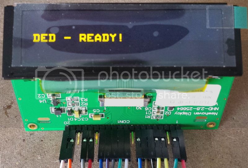
Hi
Unless you want to use highest speed, you can choose four random pins on your DUE port.
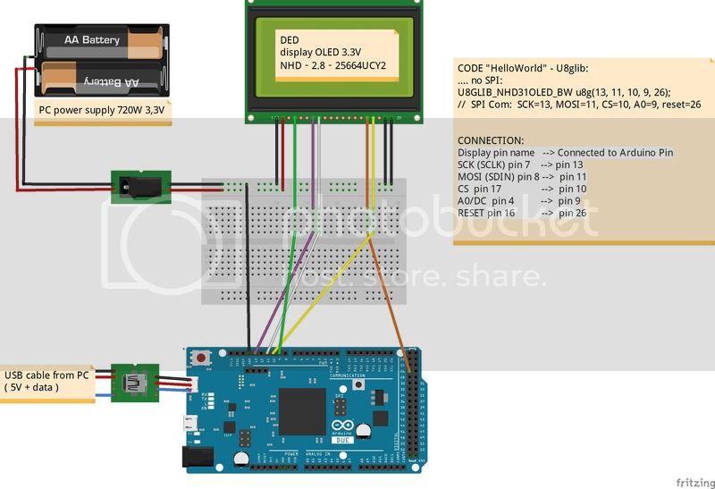
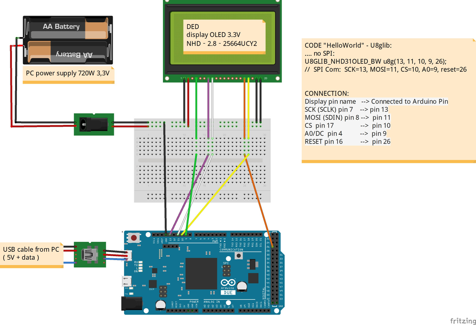
You can use 13, 11, 10, 9 or you can use anything else it does not matter as long as you tell this to u8glib.
I can not find matches between pins of the display and the Arduino DUE pin
There is no specific matching required. You can use any pins of your board. You only have to define the matching.
which pins to connect the display to which Arduino pin!
This is exactly what you have to define and write down.
The pins shown in the code "HelloWorld" by U8glib:
U8GLIB_NHD31OLED_BW u8g(13, 11, 10, 9); // SPI Com: SCK= 13, MOSI= 11, CS= 10, A0= 9
they refer to the Arduino pin or pins of the display?!?
They refer to your Arduino board. These are the Arduino pin numbers.
SCK:
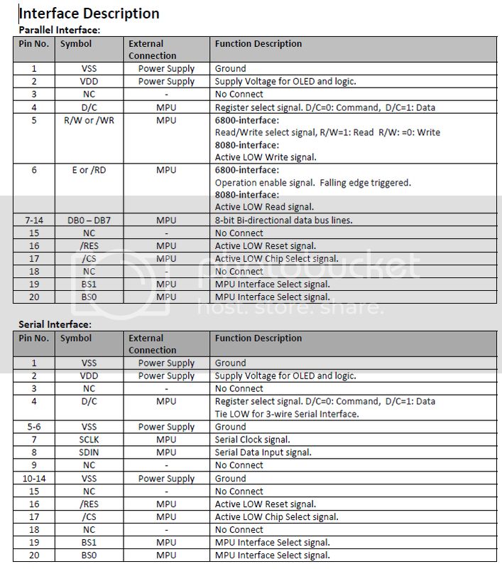
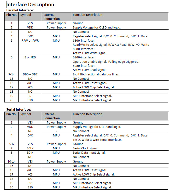
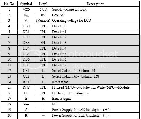
a) to which pin of the display corresponds!? the number 7? (SCLK - Serial Data Input Signal!)
b) in which pin dell'Arduino be connected? It should be connected to the SCK? (SPI connectors?)
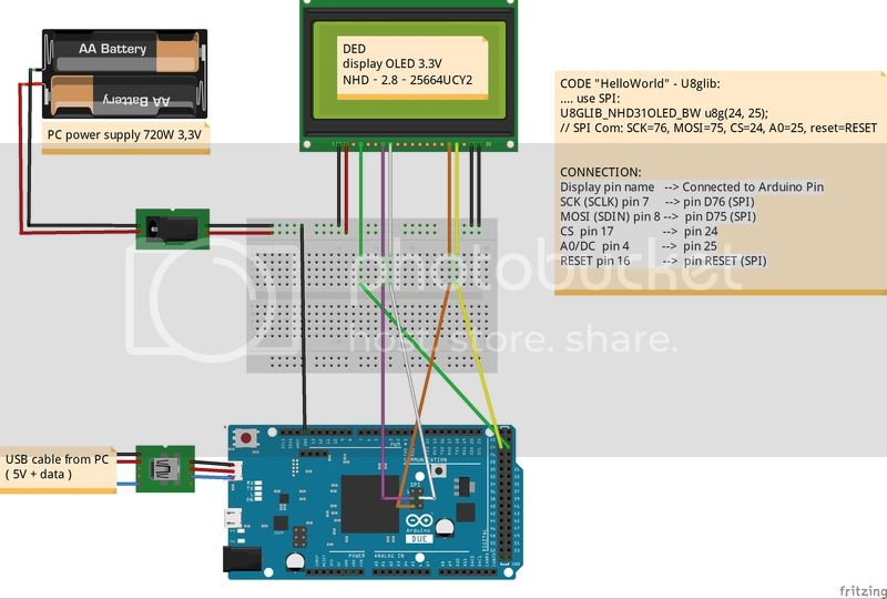
a) Yes, pin 7 of the Display.
b) Do not get confused by the lables. Again: You can use ANY pin! But of course if you want to use the SPI connector you could use pin 76. But bin 13 would be fine also if you instruct U8glib to use SW SPI.
But let us continue with pin 76.
So you would connect
Display Pin 7 with Arduino Due Pin 76.
Then later your constructor for U8glib must have the Pin Number 76 as first argument:
U8GLIB_NHD31OLED_BW u8g(76, ?, ?, ?);
Let us continue with the next pin.
MOSI:
a) to which pin of the display corresponds!?
b) in which pin dell'Arduino be connected? It should be connected to the MOSI? (SPI connectors?)
I mentioned in my last to last post (see above), that MOSI is equal to SDIN. So this is pin 8 of the Display.
Again, you could use any pin, but let us continue with the SPI connector. Hardware MOSI is there on pin 75. Again since U8glib is instructed not to use HW SPI, the actual pin does not matter. Ok, let us still use pin 75. So, please connect
Display Pin 8 with Arduino Due Pin 75.
The constructor will look like this until now:
U8GLIB_NHD31OLED_BW u8g(76, 75, ?, ?); // SPI Com: SCK= 76, MOSI= 75, CS= ?, A0= ?
CS:
a) to which pin of the display corresponds!? the number 17? (/CS - Active LOW Chip Select signal!)
b) in which pin dell'Arduino be connected?
Bingo, it is pin 17. Very good. Again you are absolutly free to choose any pin. Let me select pin 24.
Connect
Display Pin 17 with Arduino Due Pin 24.
A0:
a) to which pin of the display corresponds!?
b) in which pin dell'Arduino be connected?
I also wrote this above and this is also part of the U8glib description. This is the D/C Pin 4 of the display.
You probably will not be surprised if i sa,y that you can choose a random pin on your board for this. Let us use Pin 25.
Now connect pin 4 of your display with pin 25 of your board.
Display Pin 4 with Arduino Due Pin 25.
This will lead to the following constructor:
U8GLIB_NHD31OLED_BW u8g(76, 75, 24, 25); // SPI Com: SCK= 76, MOSI= 75, CS= 24, A0= 25
Now, let me tell you, that the constructor accept one more optinal pin: The reset pin.
Display Pin 16 (reset) with Arduino Due Pin 26.
This will finally lead to the following constructor:
U8GLIB_NHD31OLED_BW u8g(76, 75, 24, 25, 26); // SPI Com: SCK= 76, MOSI= 75, CS= 24, A0= 25, Reset = 26
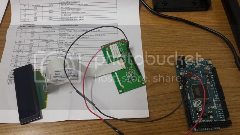
Additionally you have to select 4-wire SPI: for the Display: Connect pins 19 and 20 with GND (ok, i hope i did remember this correctly)
Then connect pin 1 (gnd) with GND and pin 2 (power supply) with 3.3V
Summery
Display Pin --> Arduino Pin
7 --> 76
8 --> 75
17 --> 24
4 --> 25
16 --> 26
1 --> GND
19 --> GND
20 --> GND
2 --> 3.3V
Constructor:
U8GLIB_NHD31OLED_BW u8g(76, 75, 24, 25, 26); // SPI Com: SCK= 76, MOSI= 75, CS= 24, A0= 25, Reset = 26
Finally, you may wonder how to activate HW SPI. This is simple: Just use this constructor:
U8GLIB_NHD31OLED_BW u8g(24, 25, 26); // SPI Com: SCK= 76, MOSI= 75, CS= 24, A0= 25, Reset = 26
Oliver