Dear All. Long time reader, first time poster, so hopefully I'm posting correctly and in the right place. But please guide me gently otherwise!
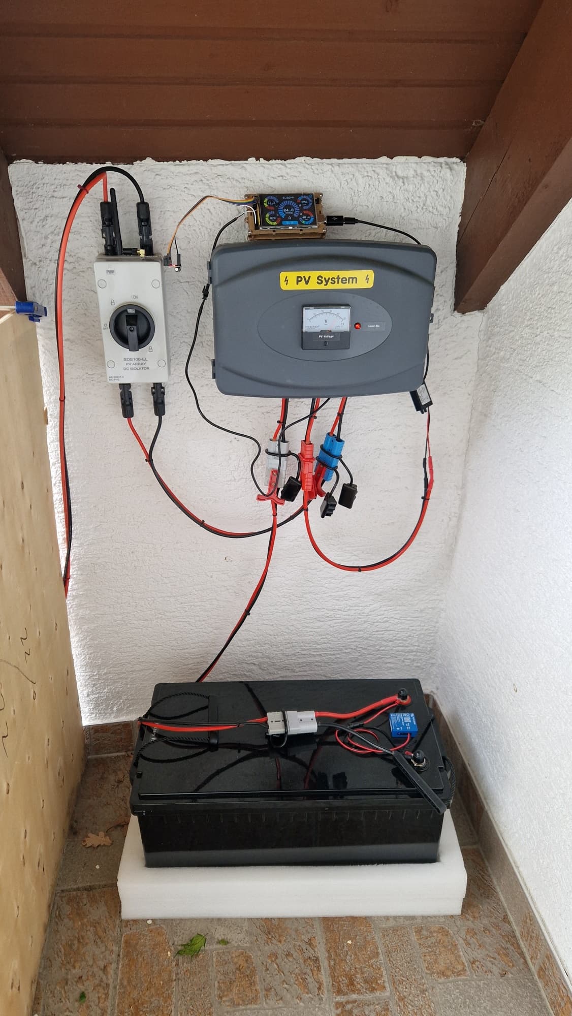
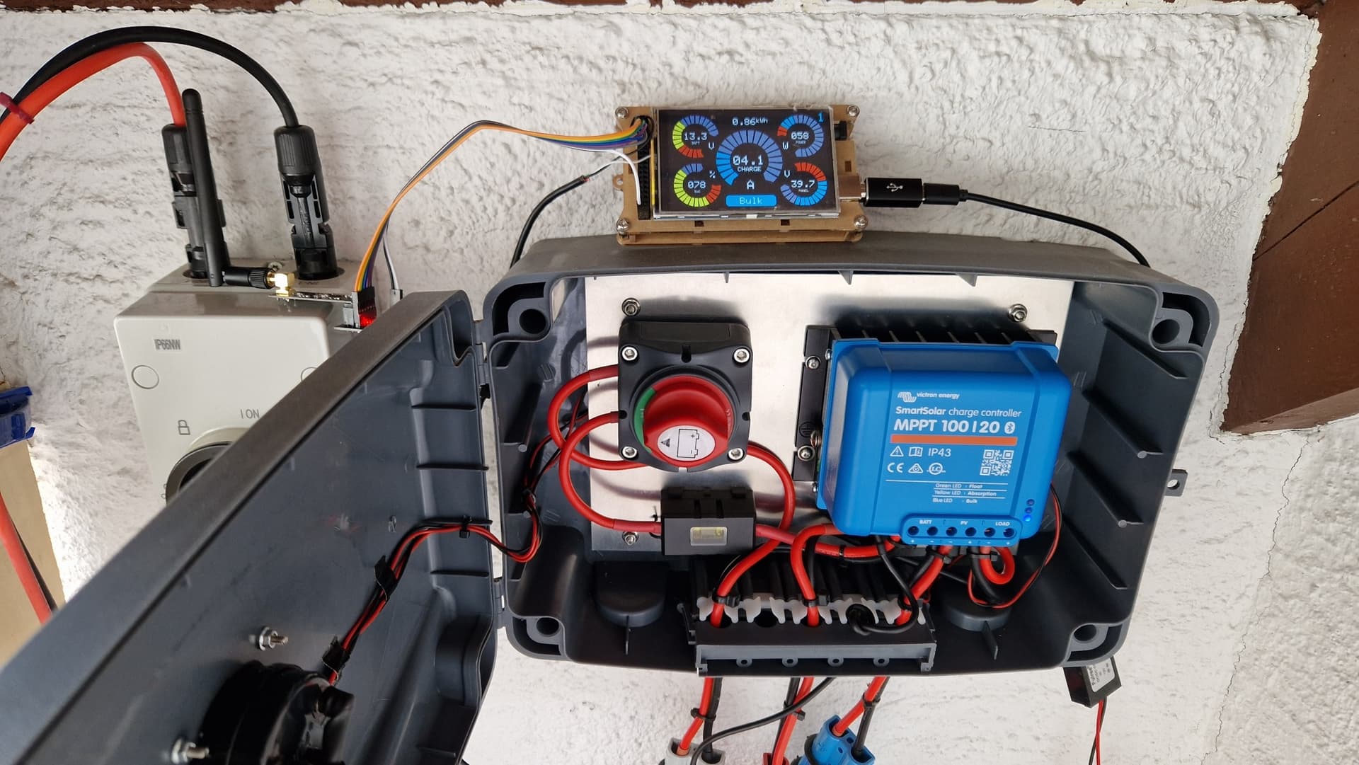
I've been working on a project to build a remote display for the serial data output from my Victron MPPT PV charge controller. The PV system is on the upstairs balcony and I wanted a display sat on my desk to see what it is doing in real time without having to look at the app on my phone or go upstairs.
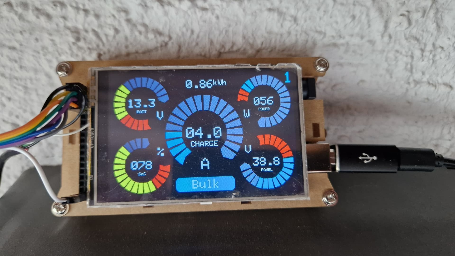
The hardware are two units consisting of Mega boards (Elegoo Mega R3 clones) with 3.5" TFTs, connected by NRF24L01+ PN & LNA radios. The NRF24's are connected via the usual module that provides a 3.3v power supply just for the radio, and this is powered from the 5v pin on the Mega. The "sender" unit reads the serial data output from the Victron charge controller, does some formatting, changes a few units and outputs some pretty gauges on the local display. It also sends the data to the "receiver" unit which just displays it nicely on my desk. Nothing too complicated or groundbreaking.
All worked fine on my desk in testing, but I was getting poor reception with the sender unit hooked up to the PV system on the balcony. I tried various settings for the radio in the software to no success, but then I found that everything worked great if I powered the sender unit from a 9v battery plugged in to the DC jack.
So the problem was obviously with the power supply coming from the load output on the MPPT controller (just a switched connection to the battery). The battery is a 220Ah 12v LiFePO4 with a peak voltage of up to 14v under charge. I tried two different power supplies to drop the 14v down before going into the Mega:
MP1584EN Ultra Small DC-DC 3A Power Downward Adjustable Module Buck Converter, adjusted to 8v into the DC input jack on the Mega (see here)
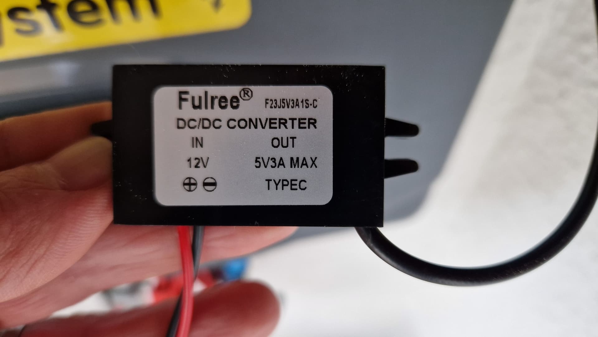
12v to 5v 3A DC-DC Step Down Adapter, giving 5v into a USB plug straight into the Mega's USB port (see here)
The USB power supply worked slightly better than the other, but still I guess 90% of transmissions didn't make it through. I added an output of the auto retry count to the sender unit to give an idea of connection quality, and this normally sat at the maximum value. So then I've spent hours reading this forums and others learning about adding capacitors and/or LC filters to the power supply.
My conclusion is that the MPPT circuitry in the solar charge controller adds some "noise" into the power supply which disrupts the NRF24 radio, even though the power goes through the 12v-5v USB regular and the 5v-3.3v regular on the NRF24 connector module.
What you will find is the MPPT is a switching device and will probably be producing the interference, also if you have an inverter working of your batteries, this can also cause problems.
Can you please post a copy of your circuit, a picture of a hand drawn circuit in jpg, png?
Hand drawn and photographed is perfectly acceptable.
Please include ALL hardware, power supplies, component names and pin labels.
Have you got bypass capacitors on the power leads that supply power to your project?
Sorry, accidentally hit post before I had finished typing... Thank you for the amazingly fast responses though! Let me add a bit more info...
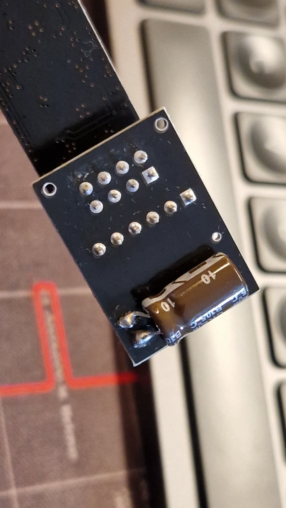
To cut to the chase, I tried adding a 10uF 50v electrolytic capacitor across the power in terminals on the NRF24 connector board (i.e. before the 3.3v local regulator). It made no difference that I could tell.
Than I tried a 100uF 50v in the same place, and it worked! The ARC counter now sits at 0 or 1 and virtually every single transmission gets through. Great - so I have a solution! I think...
But, from my reading, I understood that large electrolytic capacitors are used to prevent voltage dips when the radios transmit. And it is the smaller (0.1uF ?) SMD cap's that are already on the NRF connection module that are there for the noise filtering.
So I would like to understand why adding the 100uF cap seems to have solved the "noise" problem from the MPPT supply when I don't think there was ever a voltage dip issue because of the 3.3v reg on the module.
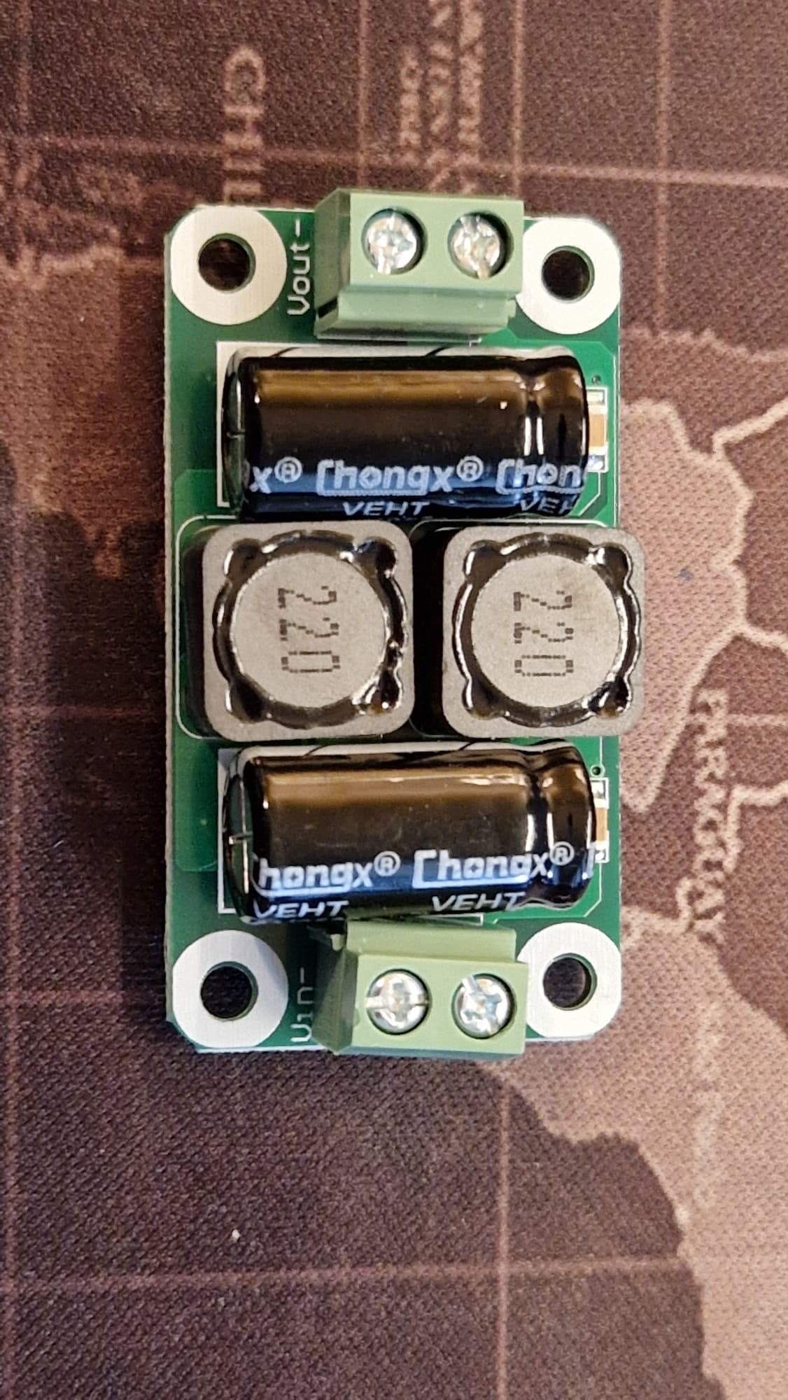
I had also ordered a " 0-50V 4A DC Power Supply Filter Board Class D EMI Suppression Amplifier for Car" (see here) before I found the solution with the 100uF cap, so I tried this today to see if it worked or was even better. It has two 470uF caps and two 220 inductors across both positive and negative lines. The result was back to having almost no transmissions making it through. It was still ok with the 100uF cap on teh radio connector module, but just the LC filter alone (added before the 12v-5v regulator) had no effect by itself.
So, what I woudl like to undersatnd is....
Why the 100uF seems to solve the MPPT noise issue, when I understood the larger electrolytic caps were used to solve voltage dip issues that I shouldn't have because of teh 3.3v reg?
Why the 100uF works, but the smaller 10uF cap didn't work and teh larger 470uF caps in teh LC filter module I board didn't?
Is just adding the 100uF cap to the radio connector (across input to 3.3v regulator) actually solving the problem fully?
The USB power supply, powered from the ~14v from the battery via the load output on the charge controller (a USB plug on the black output plugs into the USB socket on the Mega):
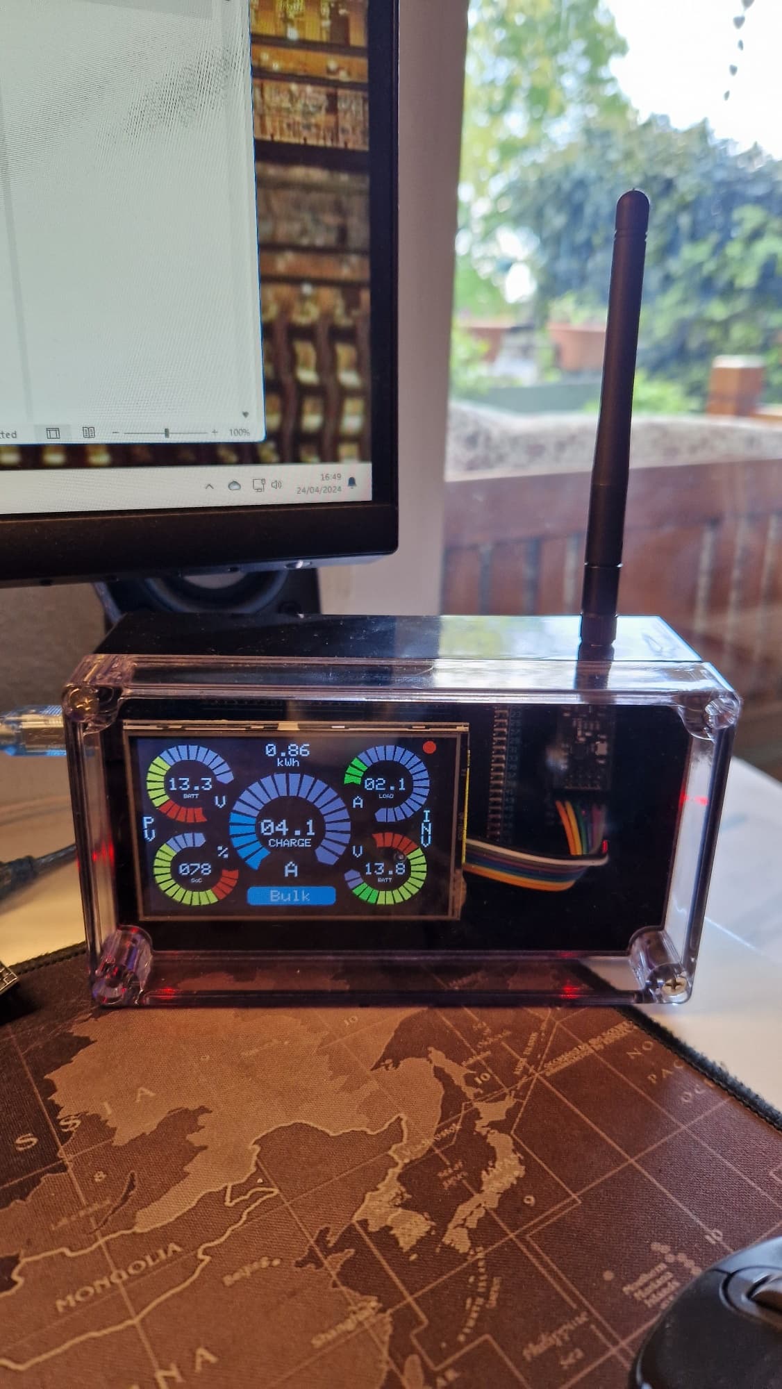
The "Receiver" unit on my desk downstairs (the INV gauges on the right side are dummy data, intended to display data from a seperate Victron inverter via a third Mega+NRF24 unit, but only once I have the current setup working reliably):
There is no inverter connected. The PV system is completely off-grid and not connected to the house. It charges the battery which I then manually move downstairs and hook up to an inverter which powers our fridge for a few days. Meanwhile a second identical battery is charging on the balcony, and I swap them back and forth. Hence the need to keep an eye on when the battery is charged so I can swap them over. Long sorry, but basically rented house and needed to keep the PV system completely separate to the house wiring.
(1) The Victron MPPT PV charge controller connects via serial to the Mega via GND and pin 19 (TX1)
(2) The NRF24L01+ radio connects to the Mega (via the connector board with 3.3v reg) via the standard pins:
Radio > Mega
VCC > 5v
GND > GND
CE > pin 48
CSN > pin 53
SCK > pin 52
MO > pin 51
MI > pin 50
IRQ > pin 49 (not needed, but plugged in to spare pin to stop it floating)
It's a simple setup, nothing else connected, and whats connected uses the standard pins.
NRF24 library:
I'm using the "RF24 Network" library by TMRh20. Channel is set to 96, data rate to 250kbps because I read this has the best range / reception, PA level set to high, LNA enabled.