Any one can help me for switch in high side of the leds supply with 12v and control by arduino pins for each row, specily in the high side.
Thank you

That will not work, the maximum voltage from a high side NPN transistor being fed by and arduino is 4.3V.
You need to generate a higher voltage signal with another NPN to feed the base of the one you have.
Why two transistor's anyway.
Hello tanks by the reply, this a very simple schm of a bigger grid 4X7 led and i need to control led rows on the high side and columns in the low side, any suggestions aside microcontrolers. Ahh ok, i need to connect the base on 12v? and the pin from the arduino on the emiter-?
I thought I just gave you one?
and i need to control led rows on the high side and columns in the low side,
That circuit is nothng like a matrix or even part of one. It has three seriese LEDs and you do not get that with a matrix.
Sorry i did not understand and i am all over google, can you make a schm?
Yes a now this was just a simple schm to try to get some help on controling the high side with a pin with a external power supply to leds
So i use a mofest on the high side 12+------ mosfet ------ leds ----- npn------ ground and in between pin of the ardunino on mosfet and npn, the irf530?
See reply #7 no FETs involved.
NEVER modify the first post, it makes subsequent answers look stupid.
Or use this:-

Thank you very much, the grd of the arduino must be common with the 12v power supply right?
paulorcrs:
Thank you very much, the grd of the arduino must be common with the 12v power supply right?
with the -ve of the 12V supply yes.
Tested and applying 5v to the transistor or not, the output voltage is the same, in fact the leds are always on.


The LED matrix pictured can be controlled in three ways - as a common column (anode) device, as a common row (cathode) device, or as a one-by-one device
Either way, 8 current limit resistors are needed.
Common column: the resistors connect to the row pins. The row pins are set high (off) or low (on), and 5V is applied to one column pin. Column is turned off, next set of row data is set up, next column is turned on. Repeat for the rest of the columns.
5V is supplied thru a PNP or a logic level P-channel MOSFET. Can also be an 8-channel device like A2982, or a shift register like MIC5891.
Common row: the resistors connect to the column pins. The column pins are set high (or) or low(off), and Gnd is applied to one row pin. Row is turned off, next set of column data is set up, next row is turned on. Repeat for the rest of the rows.
Gnd is connected thru a NPN or a logic level N-channel MOSFET. Can also be an 8-channel device like ULN2803 or an open-drain shift register like TPIC6B595.
MAX7219 also does this, with fast SPI interface, sketch then just needs to write to 8 registers to update the display, the chip does all the multiplexing.
One-by-one: the resistors may be connected to column pins or row pins.
Each position is individually controlled.
One row is driven low; one column is driven high (on) or low (off). Repeat for all columns, then move to the next row.
Alternately, one column is driven high; one row is driven low (on) or high (off). Repeat for all rows, then move to the next column.
Disadvantage - takes 8 times (or more) as long as controlling a whole row or a whole column. Display will seem dimmer as only 1 LED can be on at any 1 time vs up to 8 at a time.
Advantage - no external hardware is needed. Above methods need to Supply up to 160mA from 5V (Common column) or be able to Sink 160mA (Common row) when 8 LEDs are on.
Ok ok, so to column in + side i need pnp for each column 5v(?) i have 8 led that consume the 12v in 3 series and 2, there is no way to use those 12v without limit regulator for each column X 3 series?
What i am trying is to for example turn (C1 R8 LED) ON by on the top column C apply 12v distributed by the 8 led ( using arduinno do switch something that will let trough 12v on that column on C1 ) and then also using on pin from the arduino do set R on GRP (like a normal NPN(that one i know), my big problem is apply and controling 12v in the column with a pin from the arduino
Only using arduino pins to set high or low a column, but using a external power 12v to power the led, we all know that using direct pins to the column i can set it H or L, but i need the 12V
"my big problem is apply and controling 12v in the column with a pin from the arduino"
Yes, that will be a problem - to turn the 12V off, you need to apply 12V to the Base of a PNP or the Gate of P-channel MOSFET. The Base/Gate is then pulled low to turn the 12V on.
The prior post showed how an NPN is controlled by the Arduino, the NPN collector output then controls the Base/Gate and provides a buffer between the 12V and the arduino 5V.
Why do you want to use 12V? Your diagram in the original post does not show what you seem to describe here:
"8 led that consume the 12v in 3 series and 2, there is no way to use those 12v without limit regulator for each column X 3 series?"
CrossRoads:
Why do you want to use 12V? Your diagram in the original post does not show what you seem to describe here:
"8 led that consume the 12v in 3 series , there is no way to use those 12v without limit regulator for each column X 3 series?"
Thank you for your patience ![]()
Yes that is not the real diagram, the real diagram as 4 by 7 boxes matrix each one with 3 led so its is much easier to connect all leds in column in series but if i want to turn all on i need 12v or imagine to supply each led with 5v wire, i dont want to turn all only all at the same time, also ramdomn, and figures
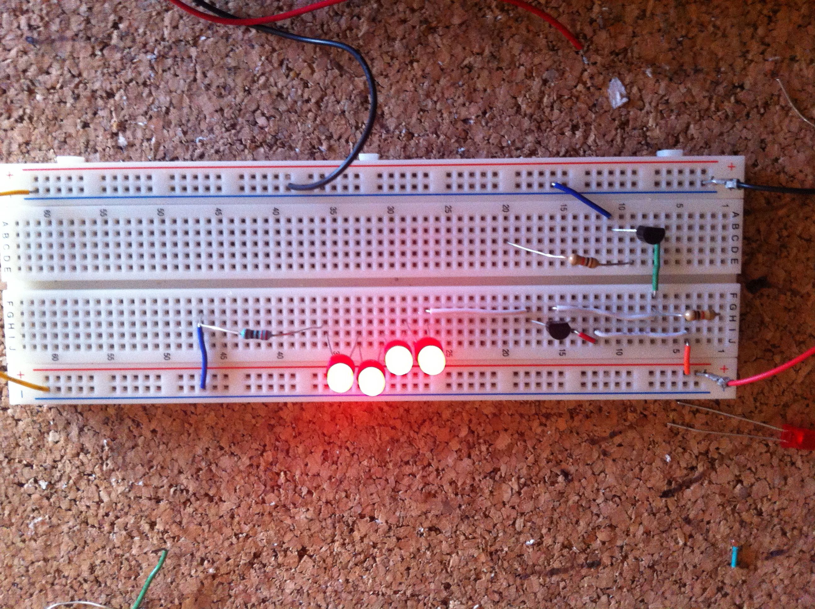
So how do i fix my problem, i did not want to use any micro controler besides arduino,here it is the picture


So in place of every LED you will have 3 LEDs in series?
The same applies:
To turn the 12V off, you need to apply 12V to the Base of a PNP or the Gate of P-channel MOSFET. The Base/Gate is then pulled low to turn the 12V on.
The prior post showed how an NPN is controlled by the Arduino, the NPN collector output then controls the Base/Gate and provides a buffer between the 12V and the arduino 5V.
So i need a NPN and PNP? can you post a schm of that? sorry the trouble. Thanks