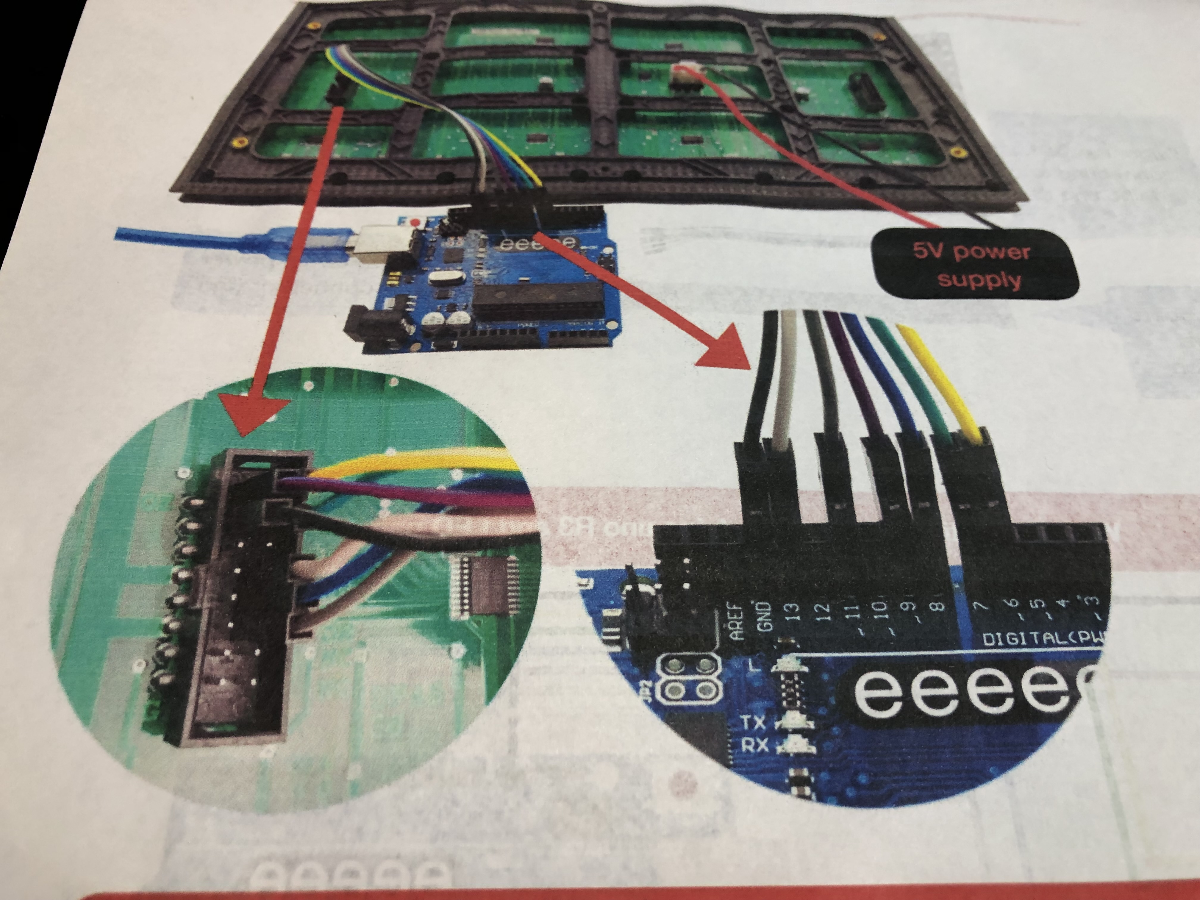
Using a P10 single color display, currently with UNO, eventually nano.
Is it possible to change / control the brightness of the display using the DMD library or do I need to use the DMD2 library?
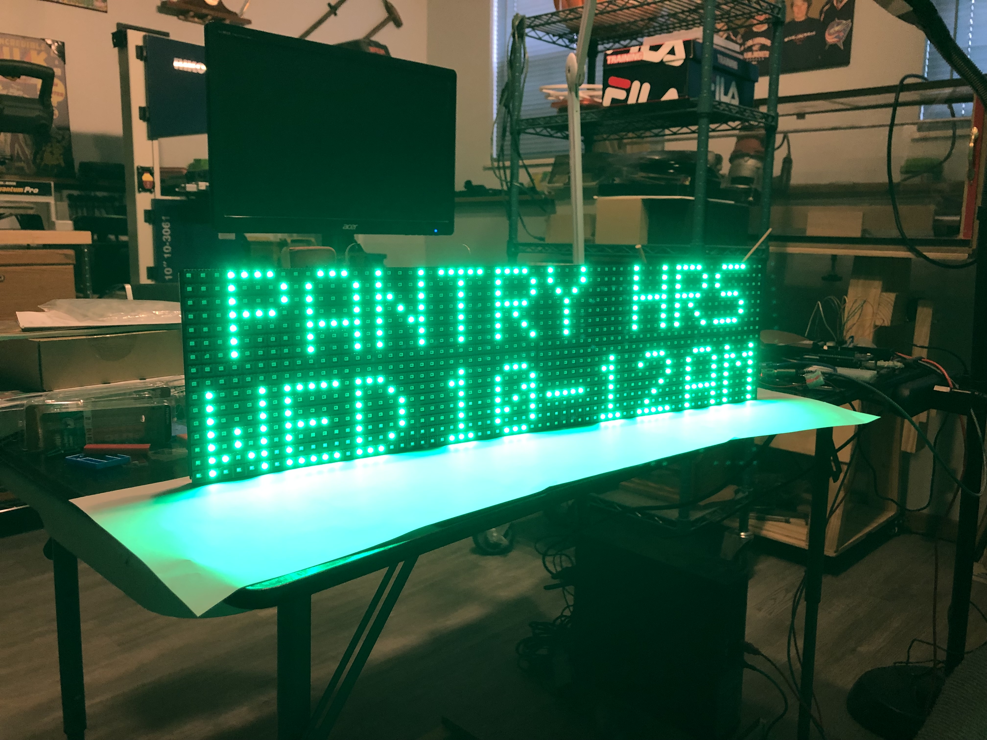
All the code works fine for a sign for the Food Pantry I volunteer at, but they now tell me they want to be able to dim the display.
#define PIN_DMD_nOE 9 // D9 active low Output Enable, setting this low lights all the LEDs in the selected rows. Can pwm it at very high frequency for brightness control.
I am able to dim the display by adding a 15 ohm resistor to the 5V line but I would like to do it via program. I want to use DMD vs. DMD2 although DMD2 dims it successfully.
I'm sorry, but judging by the code, the DMD library does not support brightness control. Working with OE pin inside the library only includes turning on and off and does not support PWM.
Adding a setBrightness() method to your sketch is not enough. To add brightness control, you need to change the library code. It might be easier to switch to DMD2.
There are also other libraries for working with monochrome DMD.
Thanks for answering.
I am not advanced enough to understand much about the code, but I noticed in the DMD code there is a line that says:
“ #define PIN_DMD_nOE 9 // D9 active low Output Enable, setting this low lights all the LEDs in the selected rows. Can pwm it at very high frequency for brightness control.”
I though perhaps experts who understand such things could help me out.
This is only a possibility; there is no support for this in the library code.
To do that, you need to add a PWM control yourself. The next issue that the Arduino has default PWM frequency about 500-1000 hz, but the DMD brightness control needs 10-20 KHz or above.
All these fixes are not too complicated, but why do this if there is already a DMD2 library if you want to run it on Arduino.
But in principle, I advise you to consider more powerful controllers, such as esp32, stm32 and rp2040. These controllers can control hundreds of panels.
Looking for guidance on how resistors work for controlling brightness on 16 X 32 red P10 led displays. I am using a nano for running my program based on DMD library and it works fine, I would just like to make a day / night display sign and hopefully prolong the sign lifespan.
I am running two P10 panels from a 5V, 4.8A (24 watt) power supply. When I measure the volts / amps with all led’s on across both panels I get:
4.1V / 3.46A (14.2W).
When I add resistors I get:
0.5 ohm resistor 4.9V / 2.02A (9.9W),
1 ohm resistor 4.9V / 1.59A (7.8W),
2 ohm resistor 5.0V / 0.86A (4.3W).
The brightness of the display decreases with each increase in ohms.
Can someone explain in simple terms why the large drop in wattage with very little resistance added is happening here?
Am I harming the P10 panels by adding a resistor / using a resistor to control brightness?
Does adding resistors and reducing the measured wattage mean less stress on the power supply?
LEDs are current devices, adding the resistor decreases the current hence it gets dimmer. Did you read the data sheet. I found this as the first line in pin description; Enable: This pin is used to control the brightness of the LED panel, by giving a PWM pulse to it. You already have an Arduino that will give you a PWM output. As you dim it the less current you will use.
Thanks. I am using the DMD library which doesn’t provide dimming through the code so no PWM. I explored that topic and came up empty, thus trying the resistors.
Simply connect one of the PWM pins to the display(s). You do not need a library to control a PWM pin and the library will have no idea if the PWM is there or not. PWM is simply an analogWrite(value) to a pin.