50% is unlikely to give enough bias for the contrast and i suspect thats why your not seeing anything, try linking contrast adjust to gnd, it might make the display too dark but enough for you to see if it's working.
The only modification is I replaced the potential-meter, with a fixed voltage divided @ 50% of supply voltage. ( dont have potential meter.)
That will almost always result in a blank display.
Most LCDs work best when the voltage at pin 3 is around 0.5 volts but many of them work acceptably when the voltage is 0 (pin 3 connected to GND).
Is it a must to have the POT?
No.
See if the LCD works acceptably with pin 3 connected to GND. If not then experiment with a different voltage divider - you want to start with about a 10 to 1 resistance ratio between the two resistors with their sum somewhere between 5 and 20 K ohms.
No If you insist on not using a pot try a 4K7 resistor from Vcc to pin 3 and a 330R resistor from pin 3 to ground (courtesy of PH Anderson) If you insist in not reading others advice you are likely to be a while getting the displays working... It would also have helped if you had taken the time to read the documentation so generously provided free of charge here for your edification.
"Most LCDs work best when the voltage at pin 3 is around 0.5 volts but many of them work acceptably when the voltage is 0 (pin 3 connected to GND)."
I am reasonably certain the poster that gave you that good advice did so because he was a little more familiar with LCD's than you... and you ought to leave the bold colored lines out of your posts, they may look good on your Etch a Sketch... however you don't see many others use them here... Maybe there's a reason, Ya Think? Really Look UGLY, Don't they?. IMO, THEY DO
There are lesser quality lcd's but the chances of getting a broken one are rare but not impossible, as your getting the blocks at switch on i'd say yours is working and if your using usb for power then the 5-10 sec you mention would fit in with the blocks appearing and disappearing while the usb port goes through the device ID proceadure, please post your code and check your wiring, especially RS & E pins 4 & 6, if they are the wrong way round it will give strange behaviour.
At the very least disconnect the whole lcd so there is no Arduino influence and just connect Power & contrast to be sure thats working first, then control lines and data
P18F4550:
There are lesser quality lcd's but the chances of getting a broken one are rare but not impossible, as your getting the blocks at switch on i'd say yours is working and if your using usb for power then the 5-10 sec you mention would fit in with the blocks appearing and disappearing while the usb port goes through the device ID proceadure, please post your code and check your wiring, especially RS & E pins 4 & 6, if they are the wrong way round it will give strange behaviour.
At the very least disconnect the whole lcd so there is no Arduino influence and just connect Power & contrast to be sure thats working first, then control lines and data
Thanks I will try solely powering just the LCD.
I am using the "hellow world" example provided. So coding is good to go.
I am using the "hellow world" example provided. So coding is good to go.
one thing i have learnt from open source is nothing is ever good to go
a lot can change between the time the tutorial page was posted and the liquidcrystal library included with the Arduino IDE so it really might help if you posted your example code,
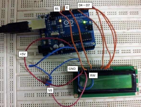
to be sure of compatability use the hello world example included in your version of IDE paying attention to this line LiquidCrystal lcd(12, 11, 5, 4, 3, 2);
yours might be different, it represents lcd pins like this
LiquidCrystal lcd( RS, E, D4, D5, D6, D7);
It's all a learning curve, which is good, if everything worked first time round we'd never learn anything