Hey folks, I've been trying to program an ATTINY85 with my Arduino Uno .. but Im having no luck at all.
I've wired up the two as laid out on a few different websites, uploaded the ISP Sketch to the Uno ... Installed several different versions of the ATTINY hoodads into ~/documents/arduino/hardware/ folder. Selected ATTINY85 1mhz clock from the boards menu ... used a 10uf capacitor to go between reset and ground and set Arduino as ISP in the programmer menu.
When I upload the Blink sketch I get these errors :
Binary sketch size: 836 bytes (of a 8,192 byte maximum)
avrdude: please define PAGEL and BS2 signals in the configuration file for part ATtiny85
avrdude: stk500_recv(): programmer is not responding
Have you tried it without the 10uF capacitor? I noticed in some situations it was not needed.
BTW:
please define PAGEL and BS2 signals in the configuration file for part ATtiny85
is normal and is not related to your issue.
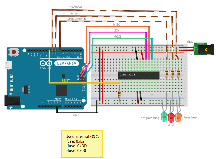
One thing you may try is to use the LED's as described in the ArduinoISP sketch to show the status of the programmer app.
// Put an LED (with resistor) on the following pins:
// 9: Heartbeat   - shows the programmer is running
// 8: Error       - Lights up if something goes wrong (use red if that makes sense)
// 7: Programming - In communication with the slave
Hello Joe, thanks for the reply. I tried it without the capacitor and still got the "avrdude: stk500_recv(): programmer is not responding" error.
I had an LED attached to pin 8, mainly for the Blink sketch and left it attached during a few of the failed programming attempts. It didn't light up at any point. I haven't tried connecting an LED elsewhere yet. There's no pin 9 so tomorrow I'll give it another go with an LED on in 7 and see if it's in communication.
When you add the three LEDs the one on attached to pin 9 (I use a yellow one) "throbs" on and off to show you that the ArduinoISP sketch is running. The LED attached to pin 7 (I use green) blinks when the Uno is talking to the ATTiny.
Embarrassingly, I think the problem was that the power rails on my bread board are not connected along the entire length of the board (on my other breadboard the rail does extend the length of the board). They need to be patched to work (the white wire in the foreground). Here's a wee video of it programming correctly. Thanks for your help folks !
I'm very happy now I can start making projects on the ATTINY85 without having to buy extra hardware to program it.
As joewez pointed out ... the capacitor was not needed on the Uno.
Attached wiring (cut up the previous images in this post to make it, credits to the original artists)
P.S. ... Does anyone know if software was used to make these diagrams, or are they hand drawn in an illustration package ? Fritzing - Electronic project sketching
I'm very happy now I can start making projects on the ATTINY85 without having to buy extra hardware to program it.
Many Trinket (Adafruit) and Digispark (Digistump) tiny85 projects run on the Arduino breadboard t85... Including libraries that are more resource friendly than the Arduino full versions!
mrburnette thank you for the link, it's always nice to have some inspiration! I'm sure I'll appreciate the slimmed down libraries once I've fallen into the rabbit hole a bit further.
I was having trouble getting more than 2 PWM pins using the Board profiles I linked earlier ... I almost had success using softwarePWM on three pins to achieve what I was going for (controlling an RGBLED and fading between choices) but the code for doing it with hardwarePWM was a hell of a lot easier to wrap my head around.
I also found this alternative ISP sketch for programming the ATTINY using the Arduino Uno:
I bricked the chips (for my purposes) by loading the wrong bootloader. Using this ISP allowed me to "fix" my unprogrammable ones. Connect PIN 9 on the Uno to PIN 2 on the ATTINY to use the Uno's crystal if you don't have a spare one laying around.