I have a relay that should be switched off when the analog value is too high by the Arduino code:
    int digitalPin = 4; // for the relay
    int analogPin = A0; // for the soil moisture sensor
    int digitalVal; // digital readings
    int analogVal; // analog readings

    void setup()
    {
        pinMode(digitalPin, OUTPUT);
        digitalWrite(digitalPin, LOW);
        Serial.begin(9600);

    }

    void loop()
    {
        analogVal = analogRead(analogPin); // read the value returned by the soil moisture sensor
        if (analogVal < 400) { // if the soil moisture sensor returns a value < 400
            digitalWrite(digitalPin, HIGH); // The water pump waters the plant
        } else {
            digitalWrite(digitalPin, LOW); // The water pump stops watering
        }
        Serial.println(analogVal);
        delay(100);
    }
But, as you can see on the video, despite going above the 400 threshold, having the relay pin switching off, it continues to pump.
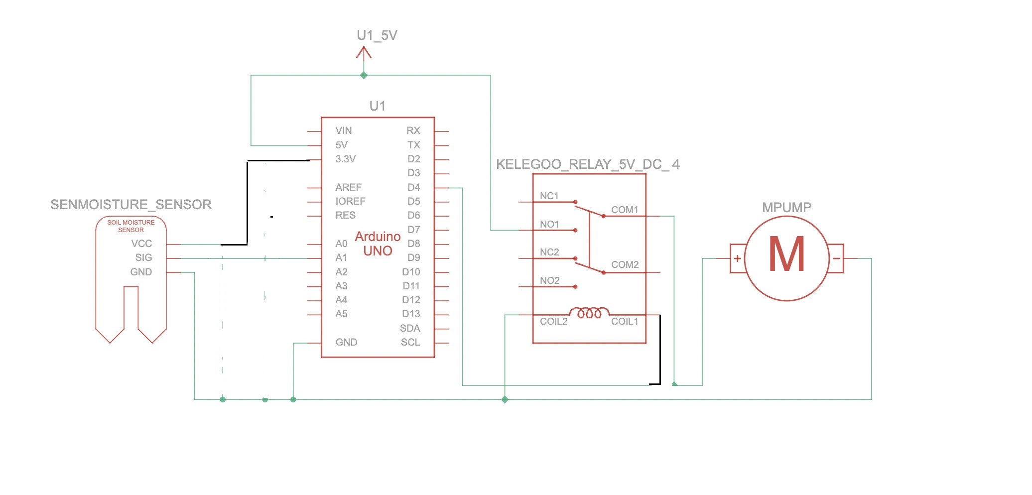
Here is my architecture, I know the. pin is wrong. it says 2 but it should be 4:
Arduinos are not power supplies, and attempting to power a relay and a pump from the Arduino 5V is pretty much guaranteed to cause trouble, if not destruction of the Arduino. Use a separate power supply for those items, and connect all the grounds.
Breadboards are intended for temporary experiments with low power logic circuits, and cannot handle motor currents. The tracks tend to burn.
Unfortunately, there are lots of bad tutorials on the web, mostly put up by people who have no real understanding of what they are doing.
Thanks for your advises @jremington ! I will find another power supply. But will that solve the problem that my pump doesn't stop despite the relay signal by the moisture sensor?
Disconnect the pump and connect your multimeter to the same terminals. Set the multimeter to resistance or continuity range. Then re-run your test. What does the multimeter show when the sensor is above and below 400?
My theory is that the relay is not switching properly. You seem to have the relay powered by 3.3V but it is a 5V relay. Maybe your pump is running because it is connected to the COM and NC terminals? EDIT: your relay board has opto-isolators, so a LOW signal will switch on the relay and a HIGH signal will switch it off. This is the opposite way to the relay board shown in the tutorial.
As @jremington says, you should not run the pump off the Arduino's 5V supply, you should avoid running high currents through the breadboard, and use heavier gauge wire to carry the motor current. It is also most important to connect a flyback diode across the motor terminals, otherwise when the motor does switch off, the Arduino, and even your laptop could be damaged.
Don't use tutorials from that site again, and advise your friends and classmates about it. Clearly the tutorials are not posted by, or reviewed by, qualified experts.
Thanks for your answer. I am a begineer with relay so I'm still copint with concepts like Non Open terminal and Normally Closed terminal. Anyway. I tried to do the modifications:
int digitalPin = 4; // pour le relais
int analogPin = A0; // pour le capteur de l'humidité du sol
int digitalVal; // digital readings
int analogVal; //analog readings

void setup()
{
  pinMode(digitalPin, OUTPUT);
  // digitalWrite(digitalPin, LOW);
  digitalWrite(digitalPin, HIGH);
  Serial.begin(9600);

}

void loop()
{
  analogVal = analogRead(analogPin);//lire la valeur retournée par le capteur de l'humidité
  if (analogVal>400){//si la capteur de l'humidité retourne une valeur 400
    digitalWrite(digitalPin, HIGH);//La pompe à eau arrose la plante
  } else { // sinon
    digitalWrite(digitalPin, LOW);//La //La pompe à eau arrête l'arrosage
  }
  Serial.println(analogVal);
  delay(100);
}
The pump has now stopped running but it doesn't run when I get the sensor out (when analogVal > 400)
Thanks for your reply @PaulRB ! I will power the pump safely but I first want to understand why it's not working as expected. I have mt multimeter back tomorrow.
I thought I had dealt with that. The sensor has high values when it says "we have enough water". So I coded the opposite way to the code shown in the tutorial:
  if (analogVal>400){//if moisture sensor gives a value higher than 400
    digitalWrite(digitalPin, HIGH);// relay gets HIGH, water pump stops
  } else { // sinon
    digitalWrite(digitalPin, LOW);// relay gets LOW, water pump works
Any way, may I connect 5V to Normally Open (upper side in this photo) or to Normally Closed terminals (Lower side in this photo) the pump always starts in the first case and never runs in the second whether the IN1 diode is on or off.
You still power relay VCC from 3.3volt. A 5volt relay module must be powered with 5volt.
Four relays on at the same time is borderline unsafe to power from the Uno.
You're still ok, because you're currently only using one relay.
You can't power a large motor from the 5volt pin of the Arduino.
Something is going to fry if you do.
The motor must have it's own separate power supply.
That could be four AA batteries in a battery holder.
If the motor stays on without driving the relay module, then the contacts inside the relay are welded together. This usually happens if you have forgotten to add a back-emf diode across the relay contacts. Try one of the other relays (after adding that diode), or give the relay a firm tap, to loosen the contact.
Leo..
Thank you @PaulRB@JCA34F Wawa and the others I can't mention ! Now it's working !
So, if'ive understood : with 3.3V this relay wasn't charged enough to switch the NC to open, am I right ?
I am now reading the link xfpd provided, Controlling AC Devices with Arduino - SAFELY to power my first Arduino project safely. Do you know how I can move from a prototype to a domestic use? Unless this is headbanging.
This is the first electronic circuit I draw! I didn't know what fritzy was. From fritzing[dot]com I guess ? I discovered KiCAD but it seemed too complex used Tinkercad. It looks nice! It even has a simulation with code integrated. But my sensor graph was going crazy, I don't know why. Don't hesitate if you have any recommendations, tips, or critics if I can get better with electronics
I chose the bipolar relay as it looked like my Elegoo relay with 4 channels (even if it has only two in my graph).
By the way, I think I will be visiting your country very soon ...
Please forgive me if I didn't understand you very well, but are you saying that this tutorial about alternating current is interesting because I am not switching A/C but switching 5V DC current? Why is it very safe? Thank you for sharing your knowledge with the noob I am.
What I thought from your previous posts was that you are only switching low voltage DC current. But then you began to talk about AC currents and you seem to have concerns about safety, so I wondered if I could have misunderstood?
Low voltages like 5V are harmless to humans. Our skins have high resistance, so at low voltage only tiny currents will flow through our bodies, which are harmless. But at 120 or 240 V AC, things become very dangerous, even lethal.
It's forum slang for a type of wiring diagram created using the "breadboard view" in the Fritzing app. These are often very difficult to read and understand, preventing forum members from helping those that post them. However, Fritzing also has a "schematic view" which can be used to produce much more helpful/useful schematic diagrams, like the one you created in KiCAD or Tinkercad.
Hi,
I've edited your schematic.
You have done well.
But you had some shorts and the gnd was not connected to the relay.
I understand that the relay you have drawn is not the one you used, which has transistor drive on its board.
Yes, I am only using the power of my Arduino to power both the relay and the motor. So should I still look for an alternative source of energy for the circuit? Or am I all right?
@TomGeorge 's, Australia. And thanks for the correction and tips TomGeorge