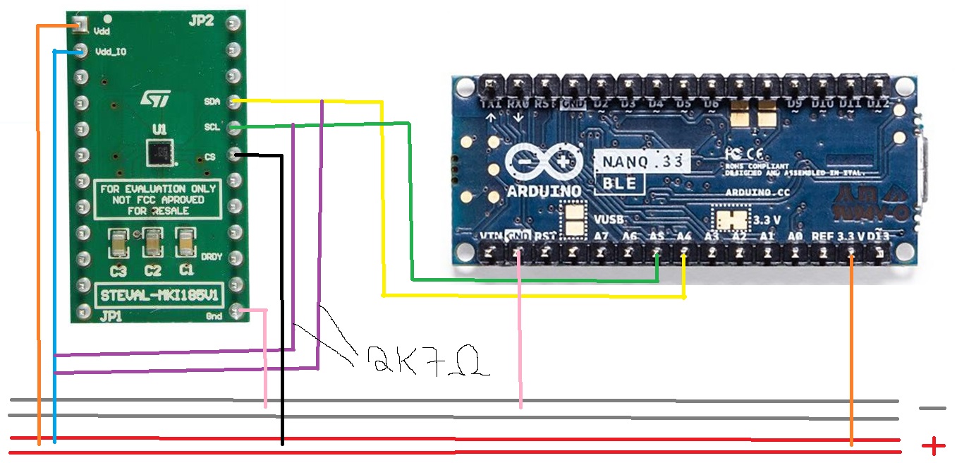
I want to read data from a magnetometer (iis2mdctr from STM) which is mounted on a socket adapter (STEVAL-MKI185V1). I connected it to an Arduino Nano 33 BLE.
Do you have another setup, board and device that talks over i2c that is known working.
If you do then substitute the sensor or nano33 to see if it still works.
the pull up resistors are certainly required when you're communicating with the CHIP itself, and not the board (wich is a module with chip's peripherals components).
I bet your module HAS pull up resistors so you don't need to add ones on your circuit.
Please note it should not be the root of your issue.
About a new I2C module: take the good habbit to test your connections with a "I2C scanner". It is a simple sketch which will give you the correct I2C adress of your module (in an HEX format number) IF the connections are ok.
This is my best advice to start because if everything works, you have 2 majors informations:
adress of your module (the only way to communicate with)
a proof that your circuit is ok (good thing to test with and without the pull up resistors).
At this point, you did well to open the datasheet (but please keep in mind datasheet is usually based on a chip, not the module carrying it).
So it is time to take a look at:
how set up the module (may be in sleep and not responding)
how to launch a measure and get the corresponding result.
for thoses last points, you may also try to use an available library, in order to compare the obtained results (or see what inside and get inspiration for your own code).
EDIT: sorry I just read you used a scanner but without proper results. Push in this direction: no I2C adress? no I2C exchange.
I have another setup with a working i2c connection, but it is soldered and inside of a prototype which i don't want to dismantle. But i ordered an Arduino Uno which is in delivery, i can test it next week.
I guess the problem is with the wiring, as i can't find good information about how to wire the iis2mdctr correctly. It is just that i know modules in general need VDD, GND, SCL and SDA for i2c communication. Then i took the information from the data sheet, that i need to connect SCL, SDA and CS to VDDIO with resistors. But i don't know if there is any other thing that i have to take care of.
your photo looks clear enough, and my remark is only about a general field. I can't see any resistor on your board, but surely some capacitors.
You must know your board is able to generate it with:
The 33BLE is a super board in my opinion. It also included a 3 axis accelerometer/gyroscope and magnetometer, wich communicates in I2C with the board (no wiring required!).
What I may propose is first to check if you're able to communicate with the inboard IMU (an I2C scanner on the board is supposed to give you 2 adresses: the IMU and the encryption chip).
If it is working, you can exclude any soft issue (like setup the board AND use properly the library) and focus of your module wiring.
If needed, I wrote my own I2C functions to use with my 33BLE. Didn't reinvent the wheels, but at least I need library no more, and it is the way I comunicate with the IMU.
The internal imo of the Nano33 is on the alternate i2c bus Wire1.
Looking for the internal imu with a scanner as a way of testing the Nano33 will lead to confusion unless you modify the standard i2c scanner program to scan on Wire1.
// I2C Scanner
// Written by Nick Gammon
// Date: 20th April 2011

#include <Wire.h>

void setup() {
  Serial.begin (115200);

  // Leonardo: wait for serial port to connect
  while (!Serial)
    {
    }
  delay(2000);
  Serial.println ();
  Serial.println ("I2C scanner. Scanning ...");
  byte count = 0;

  Wire1.begin();
  for (byte i = 8; i < 120; i++)
  {
    Wire1.beginTransmission (i);
    if (Wire1.endTransmission () == 0)
      {
      Serial.print ("Found address: ");
      Serial.print (i, DEC);
      Serial.print (" (0x");
      Serial.print (i, HEX);
      Serial.println (")");
      count++;
      delay (1);  // maybe unneeded?
      } // end of good response
  } // end of for loop
  Serial.println ("Done.");
  Serial.print ("Found ");
  Serial.print (count, DEC);
  Serial.println (" device(s).");
}  // end of setup

void loop() {}
At this point, you did well to open the datasheet (but please keep in mind datasheet is usually based on a chip, not the module carrying it).
So it is time to take a look at:
how set up the module (may be in sleep and not responding)
how to launch a measure and get the corresponding result.
You took me to the right path! I went through the datasheet again and saw that in order to get the transaction on the bus started there needs to be a start signal send from the master to the slave. I then went on to search for an library and luckily i found one on github ( stm32duino/IIS2MDC: Arduino library to support the IIS2MDC high-performance 3-axis magnetometer (github.com)) which was working right away for me! Thank you for the hint to look for how to launch a measure @GrandPete Have a nice weekend all and you especially!
Edit: I used the new Arduino Due so i don't know if it would also work with the Nano 33 BLE in case somebody else has the same problem with the same setup, i can only guess that it would work.