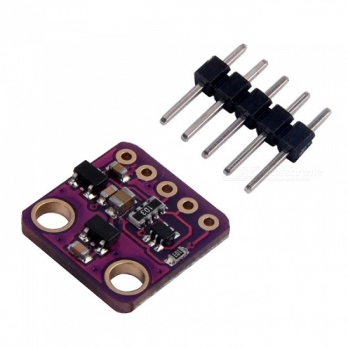
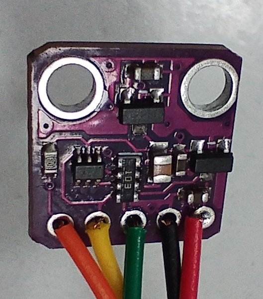
I have a GY-30102 pulse sensor (link given below) connected to Arduino Uno.
https://probots.co.in/max30102-pulse-oximeter-heart-rate-sensor-module-gy-max30102.html
The connections are as below.

I used the below i2c scanner code and the sensor is detected at i2c address 0x57.
#include <Wire.h>

void setup() {
  Wire.begin();

  Serial.begin(9600);
  while (!Serial); // Leonardo: wait for Serial Monitor
  Serial.println("\nI2C Scanner");
}

void loop() {
  int nDevices = 0;

  Serial.println("Scanning...");

  for (byte address = 1; address < 127; ++address) {
    // The i2c_scanner uses the return value of
    // the Wire.endTransmission to see if
    // a device did acknowledge to the address.
    Wire.beginTransmission(address);
    byte error = Wire.endTransmission();

    if (error == 0) {
      Serial.print("I2C device found at address 0x");
      if (address < 16) {
        Serial.print("0");
      }
      Serial.print(address, HEX);
      Serial.println("  !");

      ++nDevices;
    } else if (error == 4) {
      Serial.print("Unknown error at address 0x");
      if (address < 16) {
        Serial.print("0");
      }
      Serial.println(address, HEX);
    }
  }
  if (nDevices == 0) {
    Serial.println("No I2C devices found\n");
  } else {
    Serial.println("done\n");
  }
  delay(1000); // Wait 5 seconds for next scan
}
I used the sparkfun code given below to run the sensor.
#include <Wire.h>
#include "MAX30105.h"

#include "heartRate.h"

MAX30105 particleSensor;

const byte RATE_SIZE = 4; //Increase this for more averaging. 4 is good.
byte rates[RATE_SIZE]; //Array of heart rates
byte rateSpot = 0;
long lastBeat = 0; //Time at which the last beat occurred

float beatsPerMinute;
int beatAvg;

void setup()
{
  Serial.begin(115200);
  Serial.println("Initializing...");

  // Initialize sensor
  if (!particleSensor.begin(Wire, I2C_SPEED_FAST)) //Use default I2C port, 400kHz speed
  {
    Serial.println("MAX30105 was not found. Please check wiring/power. ");
    while (1);
  }
  Serial.println("Place your index finger on the sensor with steady pressure.");

  particleSensor.setup(); //Configure sensor with default settings
  particleSensor.setPulseAmplitudeRed(0x0A); //Turn Red LED to low to indicate sensor is running
  particleSensor.setPulseAmplitudeGreen(0); //Turn off Green LED
}

void loop()
{
  long irValue = particleSensor.getIR();

  if (checkForBeat(irValue) == true)
  {
    //We sensed a beat!
    long delta = millis() - lastBeat;
    lastBeat = millis();

    beatsPerMinute = 60 / (delta / 1000.0);

    if (beatsPerMinute < 255 && beatsPerMinute > 20)
    {
      rates[rateSpot++] = (byte)beatsPerMinute; //Store this reading in the array
      rateSpot %= RATE_SIZE; //Wrap variable

      //Take average of readings
      beatAvg = 0;
      for (byte x = 0 ; x < RATE_SIZE ; x++)
        beatAvg += rates[x];
      beatAvg /= RATE_SIZE;
    }
  }

  Serial.print("IR=");
  Serial.print(irValue);
  Serial.print(", BPM=");
  Serial.print(beatsPerMinute);
  Serial.print(", Avg BPM=");
  Serial.print(beatAvg);

  if (irValue < 50000)
    Serial.print(" No finger?");

  Serial.println();
}
The code uploaded successfully and the sensor was initialized without any error. But the red LED in the sensor didn't glow and hence the "No finger?" message came up even after placing the finger on the sensor. Is it possible that I got a defective chip with a non working LED?