I’m new to robotics. I’m using a MAX30102 (black) heart rate sensor with an Arduino Uno and testing it with the SparkFun library’s Example 5. The wiring seems fine, but the sensor’s LED doesn’t turn on, and the serial monitor keeps saying:
"Initializing... MAX30102 was not found. Please check wiring/power."
What should I do to fix this?
#include <Wire.h>
#include "MAX30105.h"

MAX30105 particleSensor;

void setup() {
  Serial.begin(115200);
  Serial.println("Initializing...");

  // Initialize sensor
  if (!particleSensor.begin(Wire, I2C_SPEED_FAST))  //Use default I2C port, 400kHz speed
  {
    Serial.println("MAX30105 was not found. Please check wiring/power. ");
    while (1)
      ;
  }

  // Setup: Reduce LED brightness to avoid sensor saturation
  byte ledBrightness = 64;  // Lower to 64 (~13mA typical) to avoid saturation
  byte sampleAverage = 4;   // Use 4 for better responsiveness
  byte ledMode = 2;         // 2 = Red + IR
  int sampleRate = 200;     // Sample faster for smoother waveform
  int pulseWidth = 411;     // Highest sensitivity
  int adcRange = 4096;      // Suitable for normal application

  particleSensor.setup(ledBrightness, sampleAverage, ledMode, sampleRate, pulseWidth, adcRange);

  // Take an average of IR readings at power up (print once for baseline reference)
  const byte avgAmount = 16;
  long baseValue = 0;
  for (byte x = 0; x < avgAmount; x++) {
    baseValue += particleSensor.getIR();
    delay(10);
  }
  baseValue /= avgAmount;
  Serial.println(baseValue);  // Print once for plotter scaling (optional)
}

void loop() {
  long irValue = particleSensor.getIR();
  Serial.println(irValue);  // Real PPG IR value
  delay(40);                // Faster refresh for smoother plot
}
Even the I2C scanner code cannot find the sensor.
I found a tutorial that says the sensor has a problem with its circuit board. It explains that you can fix it by cutting a specific line (trace) and connecting the resistor to the side of the voltage regulator. Link
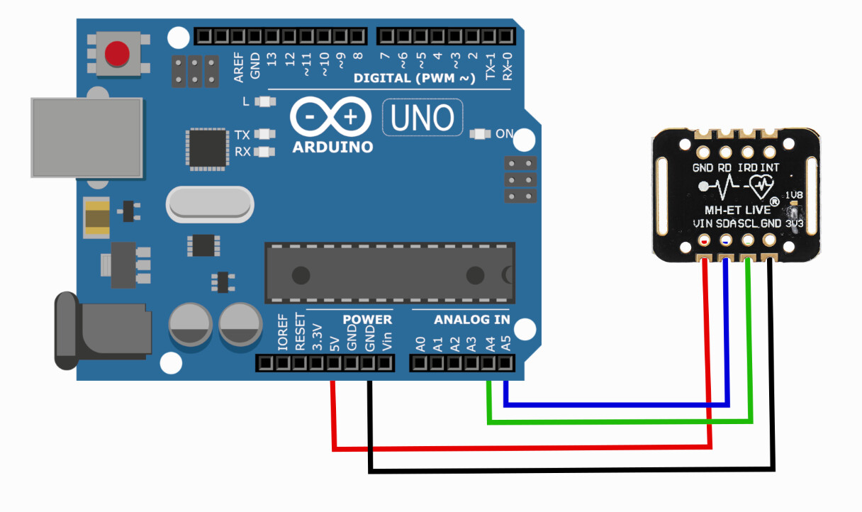
It looks like a schematic from the Internet. In order we could help you, it is important to see your real schematic rather than internet copy. Could you show a photo?
Why did you changed this? Do you change also a logic level jumper on the sensor pcb left to the GND pin?
It seems to me that the video related to the different module.
Do you really want us to help you solve your problem? Lets start with a good schematic showing exactly how you have wired it. It is like you are asking for a map to go from Sigfind to Wisend without any more information other then there will be water and grass along the way.
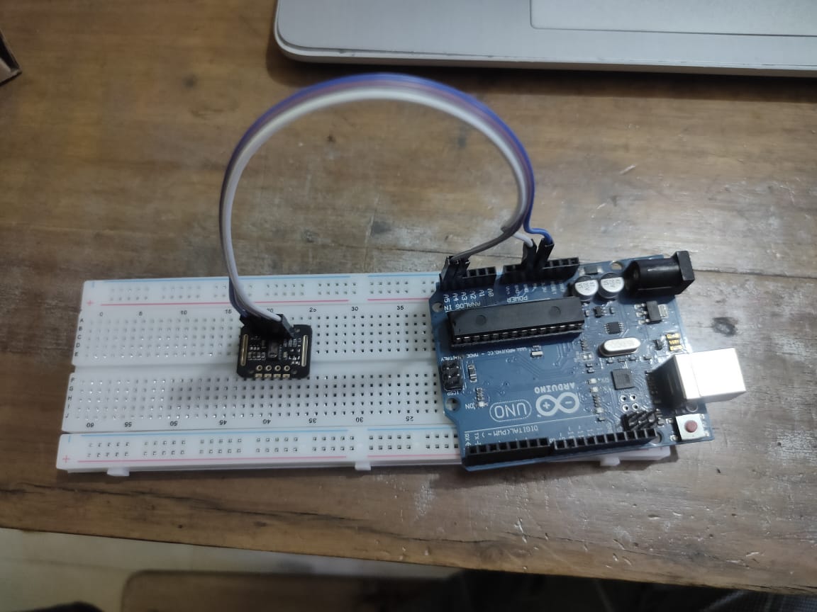
here is the photo of how I have wired the components. I used 3.3V before but when I changed it to 5V, the sensor light turned on for some time and it shows the wave form on serial plotter and values on serial monitor. But when I placed my finger on the sensor the light turned off and shows nothing. After that I removed the usb connection of arduno uno to my laptop and retried but there is no difference. I shows the same output as before
"Initializing... MAX30102 was not found. Please check wiring/power"
The wiring diagram you show in posr#1 is wrong, you have the SDA and SCL lines reversed.
Also note that the diagram shows the back of the board not the front side.
The header pins must be soldered on, otherwise the connections will be intermittent and unreliable.
So when you touch the device one or more of the connection is probably disconnected.
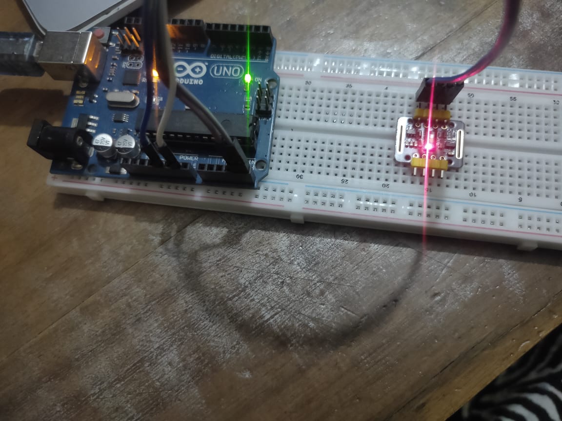
I shared the wrong wiring diagram at first on post 1, but my actual connections were correct. At first, I directly used jumper wires to connect the sensor without soldering. The sensor wasn’t detected, except for a first few seconds of connect and the led turned off when I pressed my finger on it. Thanks for your idea of soldering. I didn’t solder the pins, but I used two header pins on both sides of the sensor and now it works, and I can read data from it. Before, I tried to stick the sensor to the breadboard with just one header pin on the side of jumper wires and the sensor still wasn’t detected. Using two header pins on both sides fixed the problem. Now the sensor is sticked properly on the breadboard.