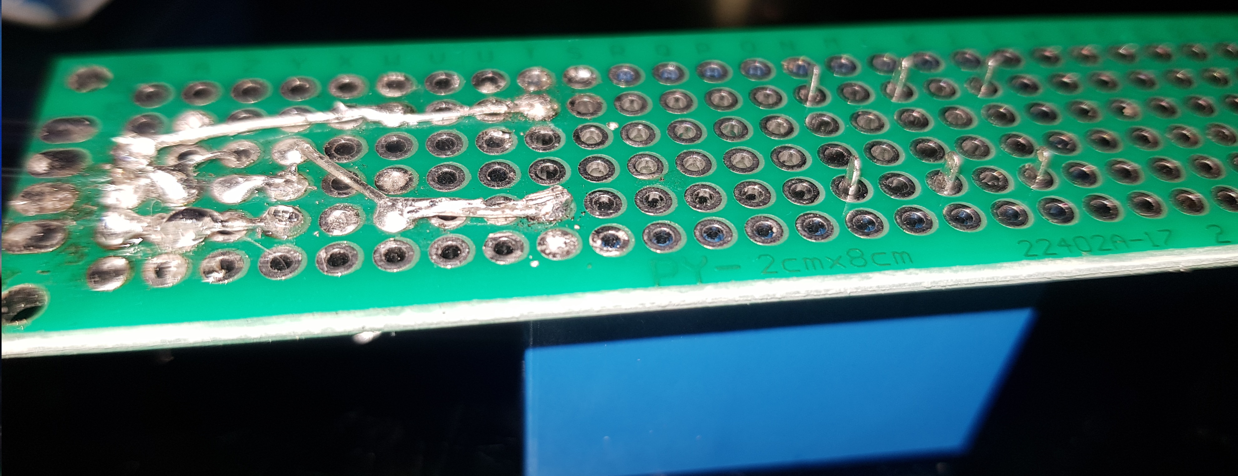
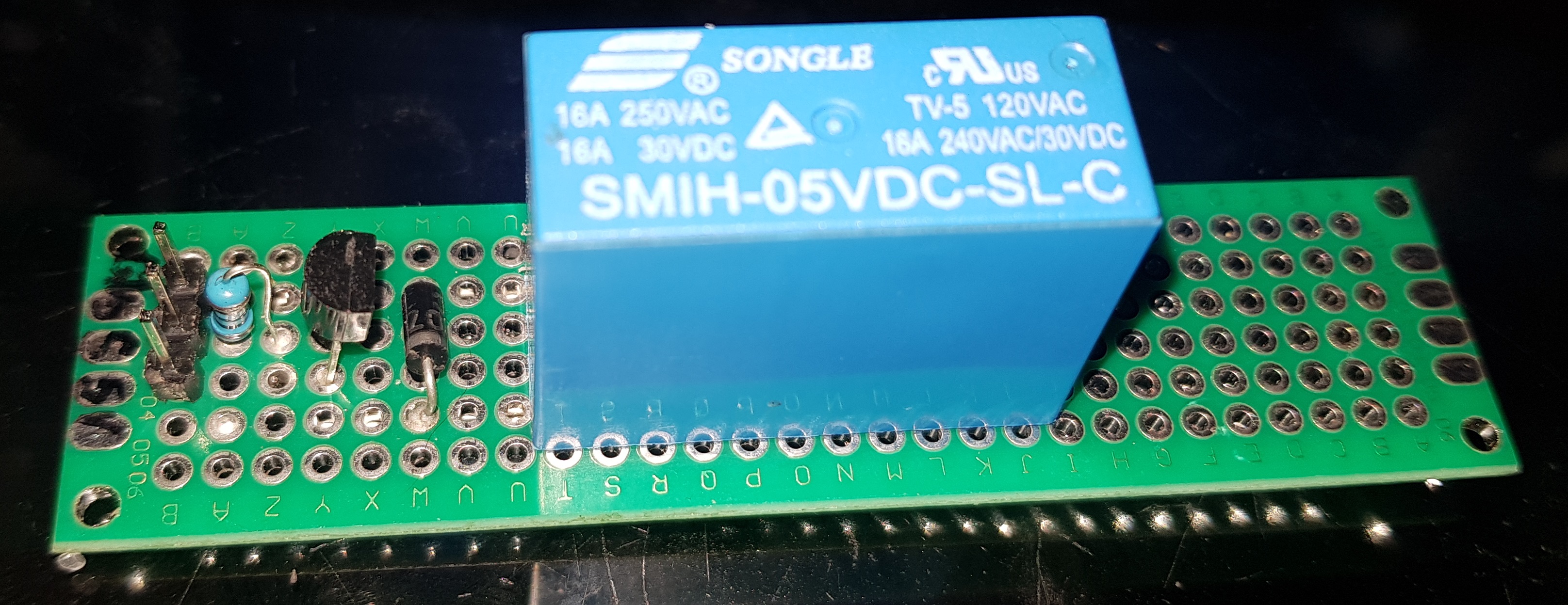
I've made a relay board to switch a relay using this simple diagram I found on circuitdigest.com
On startup it briefly triggers on off, after that it works fine. How can I prevent the relay from doing that?
Few more details witch I don't know if they are imported
I'm using a Mega 2560 R3
whit a Sensor Shield for Arduino Mega 2560 from RobotDyn aliexpress
LCD module TFT 2.4 inch
the relay is connected to pin 29
and only using usb power.
And I had this same Issue before whit a relay module I bought from aliexpress
I mange to get around the relay switching on startup or reboot by adding INPUT_PULLUP in my setup before setting the pins to outputs.
biggizmo:
And I had this same Issue before whit a relay module I bought from aliexpress
I mange to get around the relay switching on startup or reboot by adding INPUT_PULLUP in my setup before setting the pins to outputs.
Then use the same circuit/code.
Use a BC557 (PNP), with emitter to 5volt, collector to relay coil, 1k between pin/base.
Other side of the relay coil to ground, diode ring/cathode towards collector.
Could be better to change that 1k resistor to 470 ohm, for better saturation of the transistor. Assuming you have a common ~75mA blue sugarcube relay.
Leo..
biggizmo:
And I had this same Issue before whit a relay module I bought from aliexpress
I mange to get around the relay switching on startup or reboot by adding INPUT_PULLUP in my setup before setting the pins to outputs.
Wawa:
Then use the same circuit/code.
Err, no!
Using that same low-level trigger code will cause the relay to initially trigger during startup with a high-level trigger circuit.
The 10k resistor is simply unnecessary with a transistor, only necessary with a FET. (Note there is no such resistor in the circuit below.)
If the relay operates briefly on startup with a high-level trigger transistor switch, it is because you programmed it to do so!
Here is the low-level trigger relay circuit. You need to digitalWrite the pin HIGH (which is the same as setting INPUT_PULLUP but does not actually set the pin as an INPUT, so is simpler) before setting it as OUTPUT. That is all.
But for a high-level trigger relay, you must not do that.
Should have explained it better.
Those relay boards use a high-side reference with a ~2mA sink current (active LOW).
Can do the same, but without the opto isolation, with a PNP transistor as I described.
Imagine replacing the opto LED with BE of the PNP transistor.
There could of course be an issue with OP's code, which was not posted.
The NPN circuit should work.
Leo..
Use a BC557 (PNP), with emitter to 5volt, collector to relay coil, 1k between pin/base.
Other side of the relay coil to ground, diode ring/cathode towards collector.
Could be better to change that 1k resistor to 470 ohm, for better saturation of the transistor.
have tried your suggestion, also have try switching the emitter to ground and collector to 5v as that is the dereliction of the arrow. but the relay does not trigger at all then in both of those cases ???
Assuming you have a common ~75mA blue sugarcube relay.
well it is a blue relay, after some research I found some ware some more technical info naradaelectronics.rw
think it is more around 106mA
There could of course be an issue with OP's code, which was not posted.
That could be but that not explains why a relay board from aliexpres works fine but my own build one not. I can try see if I can post my code but it is rather large. But I can post parts from it
#include <Adafruit_GFX.h>
#include <MCUFRIEND_kbv.h>
MCUFRIEND_kbv tft;
#include <TouchScreen.h>
few more library's and lot more things defend but all on-relevant

#define PumpRelay   29
int  PumpState ;

void setup(){

 pinMode(PumpRelay, INPUT_PULLUP);
 pinMode(PumpRelay, OUTPUT);


}


void loop(){
 bool buttonPressed = Touch_getXY();
 Pump_btn.press(buttonPressed && Pump_btn.contains(pixel_x, pixel_y));

 if (Pump_btn.justReleased())
    Pump_btn.drawButton();
  if (Pump_btn.justPressed()) {
    Pump_btn.drawButton(true);
    PumpState++;
    Pump_relay ();
  }

}


void Pump_relay () { // Pump relay
  if ( PumpState == 1) {
    digitalWrite(PumpRelay, LOW);// Pump on
    Serial.print("\n\r");
    Serial.print("Water Pump is ON ");
    tft.fillRect(135, 60, 22, 22, GREEN);
  } else if  ( PumpState >= 2 or PumpState == 0 ) {
    digitalWrite(PumpRelay, HIGH);// Pump is OFF
    Serial.print("\n\r");
    Serial.print("Water Pump is OFF");
    tft.fillRect(135, 60, 22, 22, RED);
    PumpState = 0;
  }

}
Here is the low-level trigger relay circuit. You need to digitalWrite the pin HIGH (which is the same as setting INPUT_PULLUP but does not actually set the pin as an INPUT, so is simpler) before setting it as OUTPUT. That is all.
that looks like almost the same circuit as on the aliexp relay board,
so what your saying is add a Optocoupler (PC817 ) or something ?
My touch screen uses pin A0/A5 and bunch of other pins,
But what does it matter witch pin I use? as long as I make sure the pin can do what i need it to do.
Mega has plenty to use
setting the pin to LOW will set the relay on and keep it on, till it is set off,
a restart will trigger the relay on. same as setting it direct to output.
I think it is more the difference in electric circuit, that is causing the problem.
since the aliexp relay boards use a optocoupler and transistor,
as Paul__B shown in the diagram he posted,
that properly a better way of how I sought make my circuit,
I don't have any optocoupler laying around to make that circuit to test it,
have to look more into them to know witch one to order.
seen some relay diagrams online using 2 transistors one a PNP and the other NPN,
will give those a try