I am working on a project where I want to reverse engineer a PCB on a rangefinder. The rangefinder uses TOF to calculate the distance, so I'm assuming I can just tap the signals to the transmitter and the receiver to get an understanding of how it works, then make my own circuit that does the same. The problem is I just don't really know where to begin on this and any help would be great.
UPDATE 6/25/22: Thanks to those who helped me, I have already figured out how to reverse engineer the actual PCB layout an basic components, all I need help with is reverse engineering the chip on the board which is an ALTERA EPM3064A.
Start tapping.... What's Your education and experience regarding electronics?
1 Like
Not knowing where to begin is a basic condition of reverse engineering.  For a PCB, the idea is to "map" it to a schematic. It should be obvious to you, how that is done. Ohming it, and visual inspection. You might have to destroy it in the process, since you may have to pull parts to get some data points.
Also, what is your purpose? Fun? Learning? Cloning a commercial device so you can sell it?
Should you not provide some information about this board?
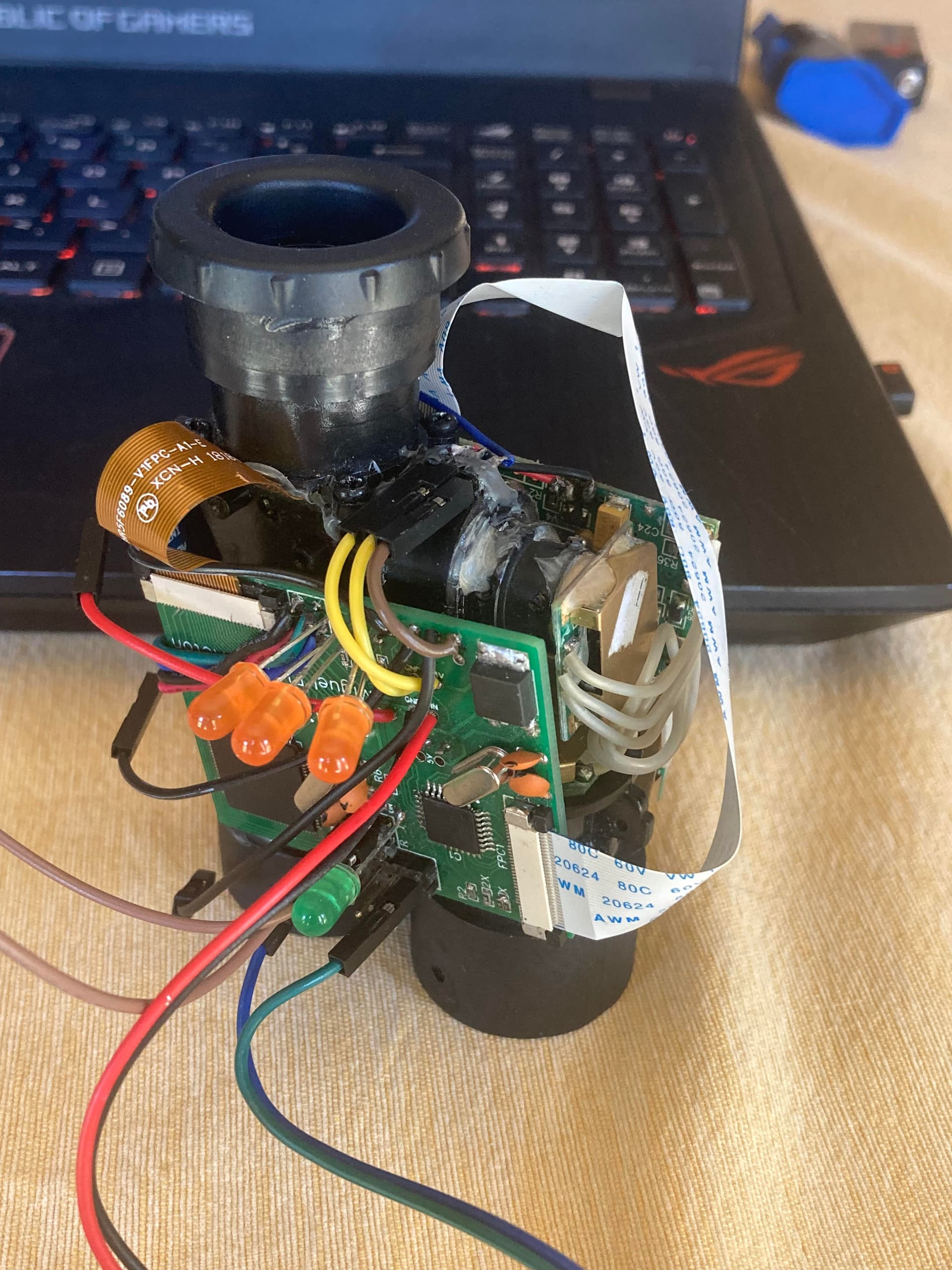
Before to achieve getting the distance, I used an Arduino nano to read and decode the output of the circuit that was meant to go to the LCD to find the distance, then do its thing and send display information through Serial to an Arduino mega which I was basically using as a custom LCD driver. I used an Arduino nano initially with the highest baud rate and analog read as a kind of oscilloscope to decode these, however now, I want to make a better design to that I can directly control the sensors.
To answer your question, I've worked with Arduino's for quite a while now, and actually started putting the ATMega's on PCBs, and I'd say I have decent experience with them as well as how circuits work.
I attached an image of my first design that is functional, just is an awful way of getting the distance from these rangefinders, as it is just intercepting the LCD signals, then outputting its own.
What circuit is that? Are we supposed to be familiar with it?
Yea, I have a multimeter and that would be a good place to start, the only problem is that they use an ALTERA chip, and I wouldn't know how to program that. And for now, I'm just doing this as a hobby project to see if I can make my own rangefinder with special features, so just for fun.
"quite a while" and "decent" don't at all help us know your experience level.
No, what I mentioned as the circuit is just the standard PCB that comes with the rangefinder to control it and i have no idea how it works
Have you done any online research on laser rangefinders? What did you learn?
Sorry, I'll try to get some more detail.
I know how to program microcontrollers. I know how to use basic tools such as multimeters, however, I do not have an oscilloscope. I know many circuitry components and how they work. I know many protocols such as I2C and UART. And have had experience having to read through datasheets to find information about sensors and chips
Almost everyone here does. How well do you know?
I know they use lasers that send signals and then calculate the time of flight and the speed of light. So for designing my own circuit, I think I'd have to use faster microcontrollers than ATMega at 16MHz, as they have to calculate nanoseconds. Also, I've seen in many of these circuits they have step-up converters to get more violate to the laser transmitter.
I know that the Arduino interface is quite a bit simplified and I know how to use some basic functions on the chips such as setting the directional registers of pins and setting up interrupts on the ATMega chips. I have basic knowledge on the architecture of these chips, but not very good understanding
You know the clock is 16MHz. How far does light travel in one clock cycle? How many clock cycles would it take to command a laser fire and obtain a return pulse? Think about it.
Even - consider the same question but 160MHz...
18m for 1 at 16MHz
1.8m for 1 at 160MHz
Yea, I'm gonna need a chip with a much faster clock.
I know ALTERA chips can be pretty fast, so I'd probably have to learn how to program those.
Actually, before the schematic, create a bill of material, BOM, for the board components.