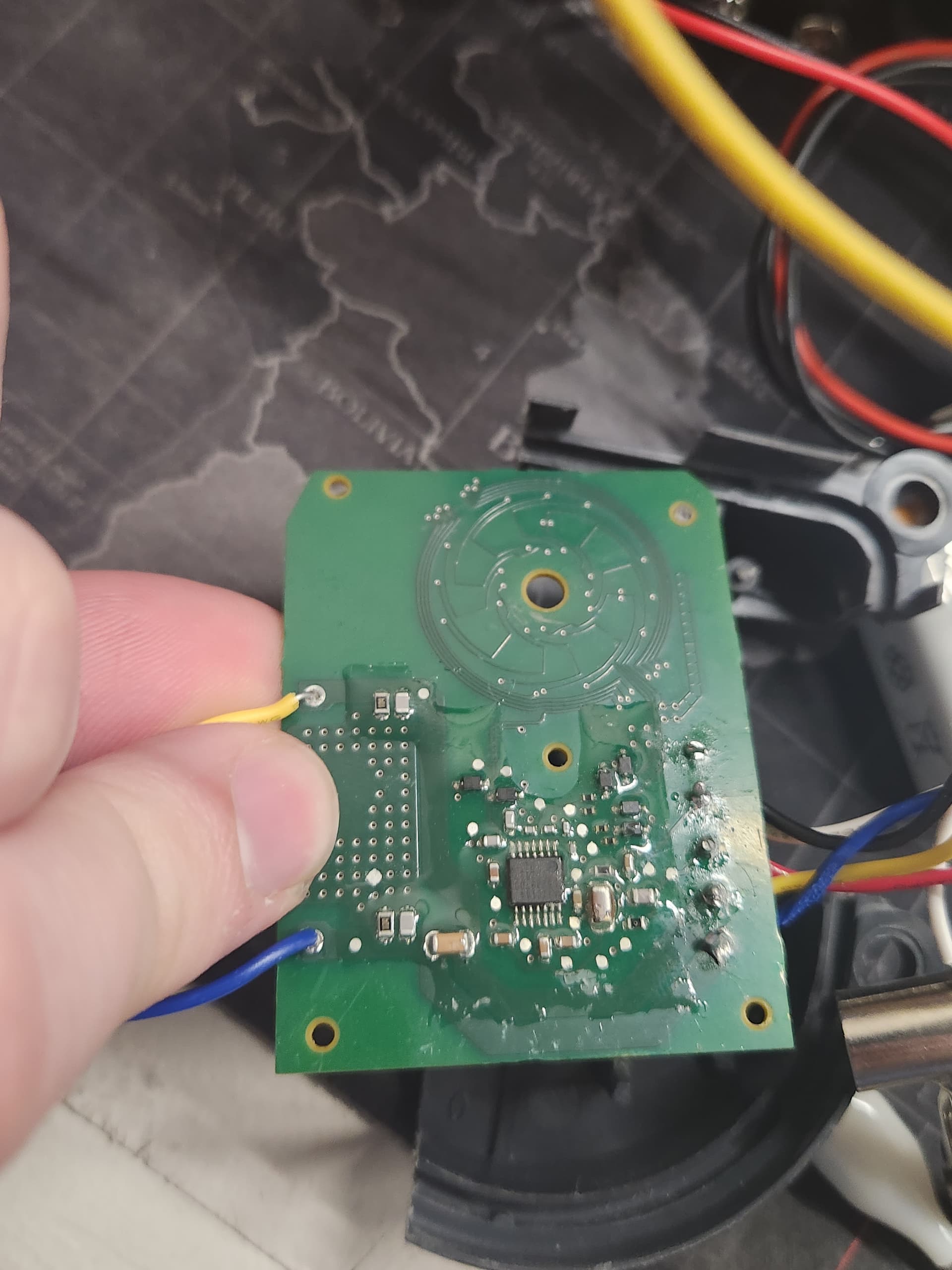
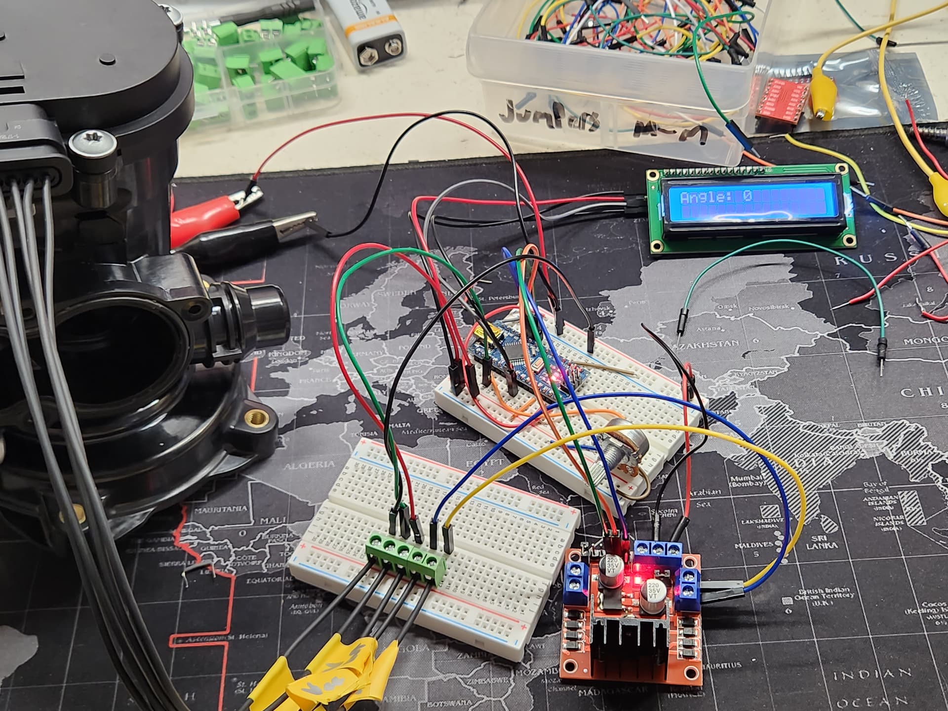
I have an unknown Coolant Control Valve I am trying to reverse engineer from the OEM part so I can test and compare potential suppliers. The Valve has pins (M-, M+, Vout, VCC, Gnd) and I know Vcc is 5V and Vout should output the position of the valve. I also know the valve is controlled by a DC motor which operates independently of the encoder that provides Vout. I am attempting to use an Arduino Nano, 10K potentiometer, LCD display, and L298N motor controller to allow me to dial in an angle based on the Vout and have the valve rotate to the set angle. I am not getting movement of the valve but instead a whine from the motor and the LCD screen fades and turns off when I hit a certain position causing the whole circuit to restart. I was hoping someone could look at my code and what I am trying to do and offer some guidance.
I am uploading a picture of the circuit that operates the valve which has an integrated encoder along with a picture of my setup.


The connections are as follows:
Power Supply
(+) - 12V rail on breadboard
(-) - Ground rail on breadboard
Nano -
Vin - 12V rail on breadboard (Right Side)
Gnd - Gnd on breadboard (both grounds rails are conencted)
5V - 5V rail on breadboard (left side)
Analog0 - Middle pin of potentiometer
Analog1 - Vout of Control Valve
Analog4- LCD bridge SDA
Analog5- LCD Bridge SCL
Digital9- ENA on L298N
Digital8- In1 on L298N
Digital7- In2 on L298N
Potentiometer:
Front - Ground
Middle - Analog0 on Nano
back - 5V rail
LCD Screen
GND- Ground rail on breadboard
Vcc - 5V rail on breadboard
LCD bridge SDA - Nano Analog4
SCL - Nano Analog5
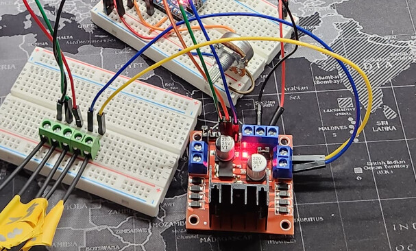
L298N
12V - 12V rail on breadboard
GND - Ground rail on breadboard
Vcc - Not connected
ENA - Digital9 on Nano
IN1 - Digital8 on Nano
IN2 - Digital7 on Nano
Motor(+) - M+ on valve
Motor(-) - M- on Valve
Coolant Valve
Gnd - Gnd rail on breadboard
Vcc - 5V rail on breadboard
Vout - Analog1 on Nano
M+ - Motor(+) on L298N
M- - Motor(-) on L298N
my code is as follows:
#include <Wire.h> // Include the Wire library for I2C communication
#include <LiquidCrystal_I2C.h> // Include the LiquidCrystal_I2C library for LCD control

#define ENA 9
#define IN1 8
#define IN2 7
#define POT A0
#define VOUT A1

LiquidCrystal_I2C lcd(0x27, 16, 2); // Initialize the LCD with the I2C address and 16 columns and 2 rows

void setup() {
  lcd.init(); // Initialize the LCD
  lcd.backlight(); // Turn on the backlight
  pinMode(ENA, OUTPUT);
  pinMode(IN1, OUTPUT);
  pinMode(IN2, OUTPUT);
  Serial.begin(9600);
}

void loop() {
  int potValue = analogRead(POT);
  int dutyCycle = map(potValue, 0, 1023, 0, 255);
  analogWrite(ENA, dutyCycle);

  int voutValue = analogRead(VOUT);
  float valvePosition = map(voutValue, 0, 1023, 0.0, 1.0);
  Serial.print("Valve Position: ");
  Serial.println(valvePosition, 2);

  if (valvePosition < 0.5) {
    digitalWrite(IN1, HIGH);
    digitalWrite(IN2, LOW);
  } else {
    digitalWrite(IN1, LOW);
    digitalWrite(IN2, HIGH);
  }

  int angle = map(valvePosition, 0, 1, 0, 180); //180 is default, set as max angle
  displayAngle(angle);

  delay(100);
}

void displayAngle(int angle) {
  lcd.setCursor(0, 0); // Set the cursor to the first column of the first row
  lcd.print("Angle: ");
  lcd.print(angle);
}