Friends, I'm working on a PCB that will drive a single motor to build a marble auger for my son. I know I could just buy a motor driver shield or what have you, but I'm also trying to learn the art of building electronic assemblies. I've done a fair bit of breadboarding practice, so now I'm looking to make something that will fit inside a 3d printed enclosure and give my son a good experience.
I've designed a PCB with the following features:
DC in from 5v power supply.
Micro-USB
Output for motor (some micro mini BDC 3-5v motor from Ebay).
Input for a POT that will be used to select motor power.
ESP32-S3. I know this is overkill to drive a pwm signal, but I have several lying around and a programming environment all set up. I won't mass produce this device so the BOM cost doesn't matter, to a first approximation.
A header for UART programming the ESP32.
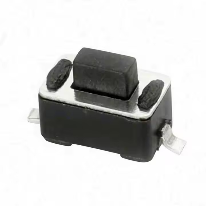
A bootsel switch.
The basic functionality is that the potentiometer will control the motor duty cycle. Once I've assembled the auger, I will test the motor and see what the reasonable duty cycle range would be, and then I'll map the potentiometer input onto the range I determine experimentally. The pot has a switch, which if open will disable the motor entirely.
Of course, this will be programmed with Arduino. Not that the programming is a huge challenge in this case.
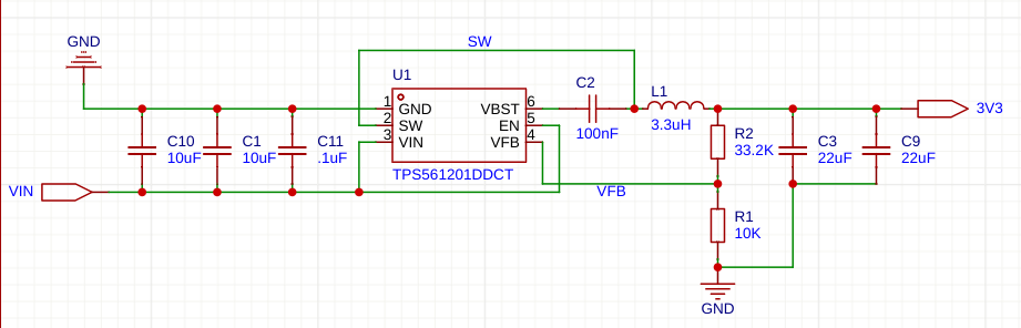
Before I order the PCB, it's my intention to test at least the motor circuit to verify that it works as expected with my power supply and ESP32-S3 devkit. However, I do not know how I can reasonably test the rest of the circuit without ordering the PCB. For example, it is difficult to install the TPS561201DDCT on my breadboard, and I don't have all those resistors, capacitors, and inductors outside of the 0603 assortment kit I'm getting.
Therefore I come to you for advice. What do you do to pretest PCBs before you order them? Is anything obviously wrong with my schematics or the PCB I've designed? I thank you in advance for any feedback! If anyone wants to dig into the schematic on EasyEDA, please let me know and I can share a link.
Gosh darn, I can't complain; you did a fantastic job doubling the bulk capacitors and adding bypass capacitors. It's smart to have the design reviewed before building; that can save a lot of headaches later in the project.
I'm not entirely sure about the 0603 parts, though. They are quite small. I've been using 0805 for a few years, and their size can be a real pain, especially if they’re placed too close together for hand soldering. That said, there’s nothing wrong with 0603s—they’ll work great if you’re comfortable with them.
I didn’t check all the schematic connections since I’m not familiar with every part, but overall, it looks good to me!
Thank you very kindly for your feedback. I will incorporate your suggestions. Just answering your interrogatories:
I haven't soldered an esp32's castellated pads.
However, I have soldered the same type of pads on a Pico-W. It was easy. The pads on the esp32-s3 module are about half as large but I think I will manage.
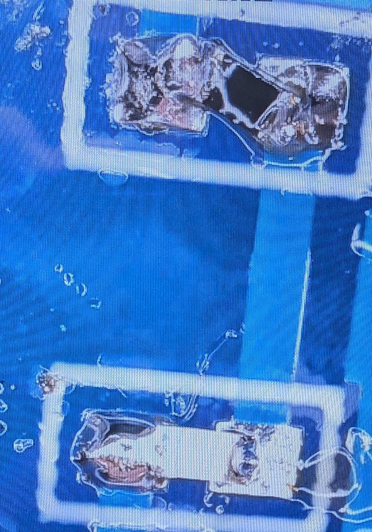
I have also soldered a ribbon cable to the pins of a Nintendo 64 CPU (PQFP -- not sure exactly the pitch but it's small). This is my work:
For this thing: that will cause a voltage drop, right? If so, that would imply reduced peak power for the motor. If it's a concern for me, should I then upgrade my power supply slightly to account for this? I.e. use a 6V supply rather than a 5V one?
I owned a contract manufacturing/electronic assembly service for 20 years. The usual sequence of someone creating a production ready circuit board was 3 tries. Did you create a bill of material, BOM, showing your components id number for your circuit board, the component source and possibly the sources part number?
Are you having a silk screen applied to your board that also has your part ids on it?
I remember an engineer with 20-30 year experience still discovered one of the components that he specified did not fit the footprint on the circuit board.