Hello,
thank you for the great forum first of all. I am trying now for some hours to get the Reader (RFID RC522 from funduino) running, but apart from some starting information I can't get it going.
I identified two different problems:
My reader pinout is a little bit different from the others (see picture), so I am not sure if I wired it up correctly.
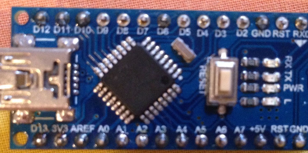
I use a chinese version of the arduino nano and the pinout may be different although I can't see any differences at the pcb. Does anyone has some experience with this sort of arduinos?
I would be so happy if the reader would work. Thank you for your help,
I tried different options, but were confused because my reader doesn't have a SDA Pin.
I used the ICSP connection in the following way but it didn't work out:
MISO-MISO
MOSI-MOSI
SCK-SCK
3V3-3V3
GND-GND
RST-RST
I tried this one but I didn't know where to put the SDA connection:
RC522 MODULE Uno/Nano MEGA
SDA D10 D9
SCK D13 D52
MOSI D11 D51
MISO D12 D50
IRQ N/A N/A
GND GND GND
RST D9 D8
3.3V 3.3V 3.3V
So as you can see at the picture the reader doesn't have a SDA Pin and I wonder how to connect it. Is it the same as the NSS pin so that I connect NSS and SS (i.e. Pin 5 at Arduino nano, which is low to start the reader)?
Hi Mike,
thank you for your help again! I checked the 3V3 question with a second power source although I remember that the RFID Sensor is using about 25 mA max at reading (see here).
Anyway, doing this I built up the complete thing again and surprisingly the reader is working perfectly.
I used the code from Miguel Balboa from GitHub with the following pin connections:
Typical pin layout used:
MFRC522 Arduino Arduino Arduino Arduino Arduino
Reader/PCD Uno Mega Nano v3 Leonardo/Micro Pro Micro
Signal Pin Pin Pin Pin Pin Pin
RST/Reset RST 9 5 D9 RESET/ICSP-5 RST
SPI SS SDA(SS) 10 53 D10 10 10
SPI MOSI MOSI 11 / ICSP-4 51 D11 ICSP-4 16
SPI MISO MISO 12 / ICSP-1 50 D12 ICSP-1 14
SPI SCK SCK 13 / ICSP-3 52 D13 ICSP-3 15
Now I am looking for the right code, but I am happy to see it working!
Hi,
For the benefit of others can you please post a copy of your circuit, in CAD or a picture of a hand drawn circuit in jpg, png or pdf?
It would make this thread self contained for any other requests for RFID help.
PS: I also tried to remove the LED on pin 13 which was suggested at some posts, but currently I use different arduino nanos (with and without LED) and there is no difference.