I tried Robin 2's simple RF24 tutorial with a nRF24L01+PA+LN to get them to communicate because I've tried many codes and none of them seem to work.
I've tried everything. I have downgraded my library version. I have put a 3.3v reducer. And have put capacitors and nothing seems to work.
When I tried Robin 2's tutorial the receiver keeps on repeating data received very quickly.
I ran Robin 2's test to test the hard ware and have added what I got. The one with only 0x00 (it wouldn’t let me tag the image but the code to test the connection between the rf module and the arduino only said 0x00) is the transmitter and the other one is the receiver. I genuinely don't know what the problem could be and any help at all is appreciated.
I am doing this for a school project to make a plane and if I don't get the transceivers to communicate soon I won't have any time to actually build the plane.
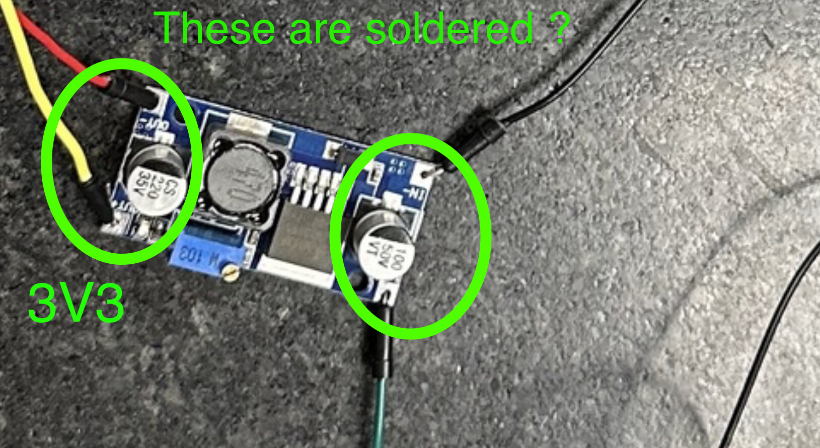
I've also added pictures of my circuits. The first one is the receiver and the second is the transmitter. Any help is appreciated. I've also tried switching the 2 modules and that didn't change anything. I suspect it is some hardware issue.
I'll be replying to messages so if you have an idea just pitch it because I'm getting kinda desperate.
Have you put some distance between the two parts meant to communicate with each other?
And… after having tried "everything", is your confidence high that none of your tests destroyed either module?
The last possibility is that one or both was non-functional when placed in your hands.
Getting to "hello world!" with this kind of thing can be frustrating, it is good that you are using software you didn't write or mess with as a first step.
You may want to go beyond Robin2 and find similar tutorials, all of which may indeed make only the same points, but perhaps enough differently so you will see a mistake you are overlooking yet.
From experience, when users have problems with these modules it almost always comes down to a power supply problem.
I note that you are using the high power versions of the RF modules which will exacerbate the problem. They can also problems when the Tx and Rx modules are close together
The best solution to powering the modules is boards like this
I have tried other tutorials as well. I was thinking that the modules I received might have been burnt out when I got them. I will order some new modules online and see if that fixes anything.
Do not use the Arduino to power those modules, the results expected are just about what you are experiencing. Get an external power supply. The 9Vpp battery is not really useful in a project like this. A few things to keep in mind.Gil's Crispy Critter Rules, they also apply to Raspberry Pie hardware:
Rule #1. A Power Supply the Arduino is NOT!
Rule #2. Never Connect Anything Inductive to an Arduino!
Rule #3 when first starting out, add a 220R resistor in series with both Input and Output pins. (LarryD)
Rule #4 buy a DMM to measure voltages, currents and resistance. (LarryD)
Violating these rules tends to make crispy critters out of Arduinos.
I have ordered new modules to make sure that’s not the issue, so I will test that soon. I have triple checked everything so that is most likely the issue.