Roland Electronic Accordion LCD Display replacement

Greetings Arduino Folks-

When I was looking for a solution to my not-specifically-Arduino problem, I remembered this site, and found a post from a farmer who had a similar issue-needing to replace a display in a piece of equipment. Like he said, “think you guys have the most experience with LCD Displays.”

https://forum.arduino.cc/t/replacing-old-lcd/599710

I am a musician and one of my instruments is a Roland FR-5 electronic accordion. When I powered it up a couple of days ago, the LCD display panel was malfunctioning. I searched online and discovered that Roland no longer supports that accordion and replacement displays are not available, even in the secondary market.

Then I found Mike, an accordion-playing tech, who said that the original displays were crap and that he had gone through three of them before he crafted a solution.

https://www.youtube.com/watch?v=OrbAWU5A4mU

Not only did Mike figure out how to replace the 48 x 84 Roland proprietary display with a commercial-grade display, but he went a step further and changed the display from a 1.5” to a 2.4” for greater readability.

He’s got a small business making these and I would have bought one in a heartbeat, but his accordion is a later model than mine. I contacted him and he said that the electronics are different and that his mod won’t work for my accordion.

As with many things I do, I’m trying to do it myself. I have some electronics background, bench wiring and building TV editing suites, so I can handle the mechanical parts. But logic configurations are above my pay grade.

So here’s what I’ve got:

1- The display interface schematic from Roland’s FR-5 Service Manual.

2- A photo of the Roland display and a reverse shot with production info for reference.

ROLAND DISPLAY 2 SHOTS

3- Nokia 5110 pinout. (Thanks to Components 101)

4- TC74VHC541FT pin assignment (Thanks to Toshiba America)

Of the 10 solder points on the Roland display, only 8 are used. Looking at the schematic, it seems to me that:

R(oland) 1 corresponds to N(okia) 8 ground
R 2-6 correspond to N 1-5 logic stuff
R 7 corresponds to N 6 vcc
R 8 corresponds to N 7 backlight (?)

Ha ha, but I could be totally wrong! So, to replace the 84 x 48 display with an original match I need to know if the 5110 would work and get the corresponding pinout.

Going further, could I substitute a 2.4” display? What would you suggest?

The absolute ultimate would be to have something a bit different. The original black-on-gray display is a bear to see when gigging in dim light. A larger display having bright white text on a black background would be the holy grail! Again, what would you suggest? Could the Roland support it?

Thanks to all for any assistance that you can give me!

/bob

Atmega328P (Uno) works with Nokia display. Bunches of display libs on GitHub.

//Function: This procedure applies to the Arduino driver NOKIA 5110 LCD.
//Time:September 4,2012
#define PIN_SCE   7
#define PIN_RESET 6
#define PIN_DC    5
#define PIN_SDIN  4
#define PIN_SCLK  3

#define LCD_C     LOW
#define LCD_D     HIGH
int count=0;
char dat[4];
char disp_tab[]={'0','1','2','3','4','5','6','7','8','9'};
#define LCD_X     84
#define LCD_Y     48
char buf[72]="A_simple_example_of_interfacing_with_the_84_x_48_pixel_Nokia_3310_LCD!!";
static const byte ASCII[][5] =
{
 {0x00, 0x00, 0x00, 0x00, 0x00} // 20  
,{0x00, 0x00, 0x5f, 0x00, 0x00} // 21 !
,{0x00, 0x07, 0x00, 0x07, 0x00} // 22 "
,{0x14, 0x7f, 0x14, 0x7f, 0x14} // 23 #
,{0x24, 0x2a, 0x7f, 0x2a, 0x12} // 24 $
,{0x23, 0x13, 0x08, 0x64, 0x62} // 25 %
,{0x36, 0x49, 0x55, 0x22, 0x50} // 26 &
,{0x00, 0x05, 0x03, 0x00, 0x00} // 27 '
,{0x00, 0x1c, 0x22, 0x41, 0x00} // 28 (
,{0x00, 0x41, 0x22, 0x1c, 0x00} // 29 )
,{0x14, 0x08, 0x3e, 0x08, 0x14} // 2a *
,{0x08, 0x08, 0x3e, 0x08, 0x08} // 2b +
,{0x00, 0x50, 0x30, 0x00, 0x00} // 2c ,
,{0x08, 0x08, 0x08, 0x08, 0x08} // 2d -
,{0x00, 0x60, 0x60, 0x00, 0x00} // 2e .
,{0x20, 0x10, 0x08, 0x04, 0x02} // 2f /
,{0x3e, 0x51, 0x49, 0x45, 0x3e} // 30 0
,{0x00, 0x42, 0x7f, 0x40, 0x00} // 31 1
,{0x42, 0x61, 0x51, 0x49, 0x46} // 32 2
,{0x21, 0x41, 0x45, 0x4b, 0x31} // 33 3
,{0x18, 0x14, 0x12, 0x7f, 0x10} // 34 4
,{0x27, 0x45, 0x45, 0x45, 0x39} // 35 5
,{0x3c, 0x4a, 0x49, 0x49, 0x30} // 36 6
,{0x01, 0x71, 0x09, 0x05, 0x03} // 37 7
,{0x36, 0x49, 0x49, 0x49, 0x36} // 38 8
,{0x06, 0x49, 0x49, 0x29, 0x1e} // 39 9
,{0x00, 0x36, 0x36, 0x00, 0x00} // 3a :
,{0x00, 0x56, 0x36, 0x00, 0x00} // 3b ;
,{0x08, 0x14, 0x22, 0x41, 0x00} // 3c <
,{0x14, 0x14, 0x14, 0x14, 0x14} // 3d =
,{0x00, 0x41, 0x22, 0x14, 0x08} // 3e >
,{0x02, 0x01, 0x51, 0x09, 0x06} // 3f ?
,{0x32, 0x49, 0x79, 0x41, 0x3e} // 40 @
,{0x7e, 0x11, 0x11, 0x11, 0x7e} // 41 A
,{0x7f, 0x49, 0x49, 0x49, 0x36} // 42 B
,{0x3e, 0x41, 0x41, 0x41, 0x22} // 43 C
,{0x7f, 0x41, 0x41, 0x22, 0x1c} // 44 D
,{0x7f, 0x49, 0x49, 0x49, 0x41} // 45 E
,{0x7f, 0x09, 0x09, 0x09, 0x01} // 46 F
,{0x3e, 0x41, 0x49, 0x49, 0x7a} // 47 G
,{0x7f, 0x08, 0x08, 0x08, 0x7f} // 48 H
,{0x00, 0x41, 0x7f, 0x41, 0x00} // 49 I
,{0x20, 0x40, 0x41, 0x3f, 0x01} // 4a J
,{0x7f, 0x08, 0x14, 0x22, 0x41} // 4b K
,{0x7f, 0x40, 0x40, 0x40, 0x40} // 4c L
,{0x7f, 0x02, 0x0c, 0x02, 0x7f} // 4d M
,{0x7f, 0x04, 0x08, 0x10, 0x7f} // 4e N
,{0x3e, 0x41, 0x41, 0x41, 0x3e} // 4f O
,{0x7f, 0x09, 0x09, 0x09, 0x06} // 50 P
,{0x3e, 0x41, 0x51, 0x21, 0x5e} // 51 Q
,{0x7f, 0x09, 0x19, 0x29, 0x46} // 52 R
,{0x46, 0x49, 0x49, 0x49, 0x31} // 53 S
,{0x01, 0x01, 0x7f, 0x01, 0x01} // 54 T
,{0x3f, 0x40, 0x40, 0x40, 0x3f} // 55 U
,{0x1f, 0x20, 0x40, 0x20, 0x1f} // 56 V
,{0x3f, 0x40, 0x38, 0x40, 0x3f} // 57 W
,{0x63, 0x14, 0x08, 0x14, 0x63} // 58 X
,{0x07, 0x08, 0x70, 0x08, 0x07} // 59 Y
,{0x61, 0x51, 0x49, 0x45, 0x43} // 5a Z
,{0x00, 0x7f, 0x41, 0x41, 0x00} // 5b [
,{0x02, 0x04, 0x08, 0x10, 0x20} // 5c ¥
,{0x00, 0x41, 0x41, 0x7f, 0x00} // 5d ]
,{0x04, 0x02, 0x01, 0x02, 0x04} // 5e ^
,{0x40, 0x40, 0x40, 0x40, 0x40} // 5f _
,{0x00, 0x01, 0x02, 0x04, 0x00} // 60 `
,{0x20, 0x54, 0x54, 0x54, 0x78} // 61 a
,{0x7f, 0x48, 0x44, 0x44, 0x38} // 62 b
,{0x38, 0x44, 0x44, 0x44, 0x20} // 63 c
,{0x38, 0x44, 0x44, 0x48, 0x7f} // 64 d
,{0x38, 0x54, 0x54, 0x54, 0x18} // 65 e
,{0x08, 0x7e, 0x09, 0x01, 0x02} // 66 f
,{0x0c, 0x52, 0x52, 0x52, 0x3e} // 67 g
,{0x7f, 0x08, 0x04, 0x04, 0x78} // 68 h
,{0x00, 0x44, 0x7d, 0x40, 0x00} // 69 i
,{0x20, 0x40, 0x44, 0x3d, 0x00} // 6a j 
,{0x7f, 0x10, 0x28, 0x44, 0x00} // 6b k
,{0x00, 0x41, 0x7f, 0x40, 0x00} // 6c l
,{0x7c, 0x04, 0x18, 0x04, 0x78} // 6d m
,{0x7c, 0x08, 0x04, 0x04, 0x78} // 6e n
,{0x38, 0x44, 0x44, 0x44, 0x38} // 6f o
,{0x7c, 0x14, 0x14, 0x14, 0x08} // 70 p
,{0x08, 0x14, 0x14, 0x18, 0x7c} // 71 q
,{0x7c, 0x08, 0x04, 0x04, 0x08} // 72 r
,{0x48, 0x54, 0x54, 0x54, 0x20} // 73 s
,{0x04, 0x3f, 0x44, 0x40, 0x20} // 74 t
,{0x3c, 0x40, 0x40, 0x20, 0x7c} // 75 u
,{0x1c, 0x20, 0x40, 0x20, 0x1c} // 76 v
,{0x3c, 0x40, 0x30, 0x40, 0x3c} // 77 w
,{0x44, 0x28, 0x10, 0x28, 0x44} // 78 x
,{0x0c, 0x50, 0x50, 0x50, 0x3c} // 79 y
,{0x44, 0x64, 0x54, 0x4c, 0x44} // 7a z
,{0x00, 0x08, 0x36, 0x41, 0x00} // 7b {
,{0x00, 0x00, 0x7f, 0x00, 0x00} // 7c |
,{0x00, 0x41, 0x36, 0x08, 0x00} // 7d }
,{0x10, 0x08, 0x08, 0x10, 0x08} // 7e ←
,{0x78, 0x46, 0x41, 0x46, 0x78} // 7f →
};

void LcdCharacter(char character)
{
  LcdWrite(LCD_D, 0x00);
  for (int index = 0; index < 5; index++)
  {
    LcdWrite(LCD_D, ASCII[character - 0x20][index]);
  }
  LcdWrite(LCD_D, 0x00);
}

void LcdClear(void)
{
  for (int index = 0; index < LCD_X * LCD_Y / 8; index++)
  {
    LcdWrite(LCD_D, 0x00);
  }
}

void LcdInitialise(void)
{
  pinMode(PIN_SCE, OUTPUT);
  pinMode(PIN_RESET, OUTPUT);
  pinMode(PIN_DC, OUTPUT);
  pinMode(PIN_SDIN, OUTPUT);
  pinMode(PIN_SCLK, OUTPUT);
  digitalWrite(PIN_RESET, LOW);
  digitalWrite(PIN_RESET, HIGH);
  LcdWrite(LCD_C, 0x21 );  // LCD Extended Commands.
  LcdWrite(LCD_C, 0xB1 );  // Set LCD Vop (Contrast). 
  LcdWrite(LCD_C, 0x04 );  // Set Temp coefficent. //0x04
  LcdWrite(LCD_C, 0x14 );  // LCD bias mode 1:48. //0x13
  LcdWrite(LCD_C, 0x0C );  // LCD in normal mode.
  LcdWrite(LCD_C, 0x20 );
  LcdWrite(LCD_C, 0x0C );
}

void LcdString(char *characters)
{
  while (*characters)
  {
    LcdCharacter(*characters++);
  }
}

void LcdWrite(byte dc, byte data)
{
  digitalWrite(PIN_DC, dc);
  digitalWrite(PIN_SCE, LOW);
  shiftOut(PIN_SDIN, PIN_SCLK, MSBFIRST, data);
  digitalWrite(PIN_SCE, HIGH);
}
void gotoXY(int x, int y)
{
  LcdWrite( 0, 0x80 | x);  // Column.
  LcdWrite( 0, 0x40 | y);  // Row.  

}
void setup(void)
{
  LcdInitialise();
  LcdClear();
  LcdString("Hello World!");
  LcdString("The count is");
  gotoXY(0, 3);
  LcdString("++++++++++++");
  LcdString("----over----");
  LcdString("--- over ---");
  //LcdString(buf);
}
void dispcountt(int count)
{
  LcdCharacter(disp_tab[count/10000]);
  LcdCharacter(disp_tab[count/1000%10]);
  LcdCharacter(disp_tab[count/100%10]);
  LcdCharacter(disp_tab[count%100/10]);
  LcdCharacter(disp_tab[count%10]);
}
void loop(void)
{
  gotoXY(0, 2);
  LcdString("**");
  gotoXY(16, 2);
  dispcountt(count);
  count++;
  LcdString("**");
  delay(200);
 
  gotoXY(0, 2);
  LcdString("==");
  gotoXY(16, 2);
  dispcountt(count);
  count++;
  LcdString("==");
  delay(200);

}

Full code attached. A very old sketch, may need updating for new IDE.
Arduino_NOKIA_5110.zip (350.6 KB)

Moving from a 5110 to another display may be much more difficult since the Roland signals and fonts (char generator) would need to drive a new display at a different resolution. There are 2 approaches (maybe more):

  • Capture the Roland's display signals with a uC, build the 5110 display in the uC SRAM, read this display buffer and output that through another display library and drive the new display.
  • Go deeper into the Roland and hopefully capture an SPI or I2C signal that are driving the Roland's display chip (assuming a separate chip.)
    Atmel note on driving LCD segments (PDF)

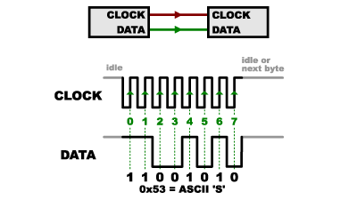
Decoding LCD datalines

Were this being done as a product, the approach would (likely) be programmable logic: ASIC

Also, Nokia displays can develop nasty electrical issues:

Thank you, mrburnette-

I certainly have homework ahead of me! In either of the cases you mention, using a 5110 or driving a new display at a different resolution, I would still have to "Capture the Roland's display signals with a uC" to determine what they are, right? How would I do that? I have an original UNO.

It's those pesky unnamed Roland pins 2-6 from their schematic. I can't tell a PIN_RESET from a PIN_SCLK or a PIN_SCE. I am leery of connecting anything that could compromise the Roland circuits for fear of seeing a $5000 instrument flatlined. Can this analysis be done non-destructively through the UNO? How would I go about it?

The troubling shooting for FR-5 is about useless:

... But, the tidbit mentioned about contrast is interesting: the problem may not be the display, buy further up in the electronics. A certified repair shop would have a diagnostic test procedure to isolate the fault; or simply "substitute" the display and then dig-in if display was filled out.

Mike likely has the answer for how Roland engineer there system. As s/he has a product they may be reluctant to provide more info; but in my experience manufacturers do not jump quantum leaps in similar models; likely while your FR-5 cannot use the retrofit LCD, knowledge of how that part functions (connections and where and black-box concept) would lead you closer to a solution.

With the Nokia LCD, contrast is a computed numeric within the processor script but with displays like LCD 1602, the contrast is the wiper connection from a potentiometer.

Without schematics, LCD model/wiring, or a decent service manual I really don't feel that I can offer more ideas. At this point, I can only guess the display is defective. Have Roland forums discussed numerous LCD failures?

All great suggestions, thank you. There have been similar issues reported in a few forums I've found. Unfortunately the only successful resolutions point to Mike Dubrovsky and his FR-7x!

"in my experience manufacturers do not jump quantum leaps in similar models."

I was thinking the same thing, and am going to write to Mike to see if I can get any insight into his methodology. Yes, I realize that he may have some reluctance, but I have communicated with him before and he knows that I would love to buy his product, if only it worked for me.

Very cool that you dug up that contrast setting adjustment from the Roland User Manual! Yes, I have tried it. It helps a bit, but as you can see from this photo, there's a lot of information on a 3 cm x 2 cm display.

Making it worse, the display is ± 9 inches from my eyes and directly beneath my head. I normally wear 1.25 reading glasses, but would need at least 2.5 or 3.0 to adequately see the displayed info. That would throw off the rest of my vision for reading charts on an iPad or music stand.

So you see why I am leaning toward the larger/brighter display solution.

I do have the complete service manual pdf which contains a set of schematics and can send it to you. Unfortunately I don't have access to Acrobat Pro to break out the relevant pages. Thinking about what you said in your last post, I revisited the specific schematic that I had clipped and expanded it a bit farther, beyond the TC74VHC541FT chip.

Now I see that there are five named logic inputs A1 - A5 which correspond to the Y1 - Y5 outputs that connect to the LCD. I realize that even though I can guess what some of these are, I still don't know the parameters. Would it be possible to use a Logic Analyzer like this one to find out?

https://www.sparkfun.com/products/18627

In doing this I would be trying to follow your suggestion to

"Capture the Roland's display signals with a uC, build the 5110 display in the uC SRAM, read this display buffer and output that through another display library and drive the new display"

Even though it will take me ages to suss it out and make that work, I think the self-education it would require would make it a doubly-worthy goal.

The 74VHC541FT IC is a Octal Bus Driver with a straight-forward logic table:

As such, purchase of a Logic Analyzer for this area of circuitry would (IMO) be of little value.

Replacing the LCD with a different type/size/pixel density is likely done by "Mike" by capturing the SPI signals that feed the 74VHC541FT
image

Beyond the mental exercise in theorizing Mike's replacement display, I do not feel qualified to advise on a route forward to replicate Mike's efforts. A logic analyzer at this point may not be particularly useful. The display controller reference would be the most valuable resource as that is where SPI is translated into controller-commands to drive the matrix.

Since Mike communicated previously that his mod is not a replacement for your instrument, I suspect the display-controller specifics are the primary stumbling issue. Otherwise, my guess is the SPI bus is not the issue.

Good luck, moving forward is a steep climb IMO; my thinking is Mike was able to find a larger display with the same/compatible controller. But, he could just as well taken the SPI into a microcontroller and manipulated the commands/data and regurgitated an SPI signal for a completely different SPI display ... or an I2C display.

GLCD "simple" displays are still very complexed engineering wonders:

Dear mrburnette,

Sorry, I've been away and my laptop can't access the Arduino Forum. Ha ha, too old to upgrade the browser.

Thank you so much for the invaluable help that you have given me! My plans going forward-

  • I will reach out to Mike.

-I've downloaded the Arduino IDE onto my desktop computer and am re-learning a lot of basics so that I can do some work with displays and begin to understand them.

-I'm trying to get a handle on how SPI works.

Maybe a fool's errand, but I am happy to get a better understanding of these systems.

If I show any progress, I'll put more info on this thread to update, hopefully beating the 6-month deadline.

One last question. Going back to the Roland LCD schematic, it looks like pin7, as well as Pin 20 the74VHC541FT IC , is getting 5v from the voltage regulator LP2981AIM5.3.0 IC. But what is that circuit off of LCD Pin 8? It looks like it's sending 5v out?

Thank you again for your patience. I hope that you had a great weekend!

Referring to your post #*: NOT five volts, That's a 3.x volt regulator

It is a power filter:

  • ferrite bead L66
  • stabilizer cap C391
  • high-freq bypass cap C392

Lots of online stuff, but this is rather clear:
Introduction to SPI Interface | Analog Devices

SPI Serial Peripheral Interface (SPI) - SparkFun Learn

It's a "synchronous" data bus, which means that it uses separate lines for data and a "clock" that keeps both sides in perfect sync. The clock is an oscillating signal that tells the receiver exactly when to sample the bits on the data line. This could be the rising (low to high) or falling (high to low) edge of the clock signal; the datasheet will specify which one to use. When the receiver detects that edge, it will immediately look at the data line to read the next bit (see the arrows in the below diagram). Because the clock is sent along with the data, specifying the speed isn't important, although devices will have a top speed at which they can operate (We'll discuss choosing the proper clock edge and speed in a bit).

alt text

One reason that SPI is so popular is that the receiving hardware can be a simple shift register. This is a much simpler (and cheaper!) piece of hardware than the full-up UART (Universal Asynchronous Receiver / Transmitter) that asynchronous serial requires.

All those Sparkfun tutorials-excellent!

This topic was automatically closed 180 days after the last reply. New replies are no longer allowed.