SB Components Micro RP2040 and ST7789 2.4 TFT LCD SPI display not working together using any library

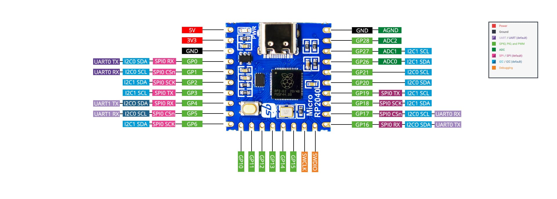
I have a board from SB components called the Micro RP2040 (Link to this product - here).

With this I also have a 2.4 inch SPI TFT LCD screen with an ST7789 controller (Link to the screen - here, it's on that page just scroll down)

Before using the RP2040 Micro board to run this display, I decided to start by using an ESP32 Dev Module to try out the display and see how it works. This display was advertised as having an ILI9341 controller but using the Adafruit ILI9341 library I was not able to fill the full screen with the content being printed. I diagnosed and fixed this error from this thread on the Arduino Forum.

From @david_prentice's answer in that thread I was able to figure out that my display has a ST7789 controller instead of the ILI9341 that it was advertised to have. This was a great relief as it proved that the display does work properly when used with the Adafruit ST77XX library.

I used this same library and changed the code for the pinout of the RP2040 Micro, when I connected it all up (through 10k resistors because the RP2040 board is 5V), all I get is a white screen.

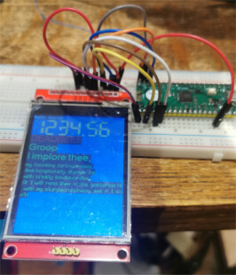
Before with the ESP32 it was working perfectly and here's an image of that -


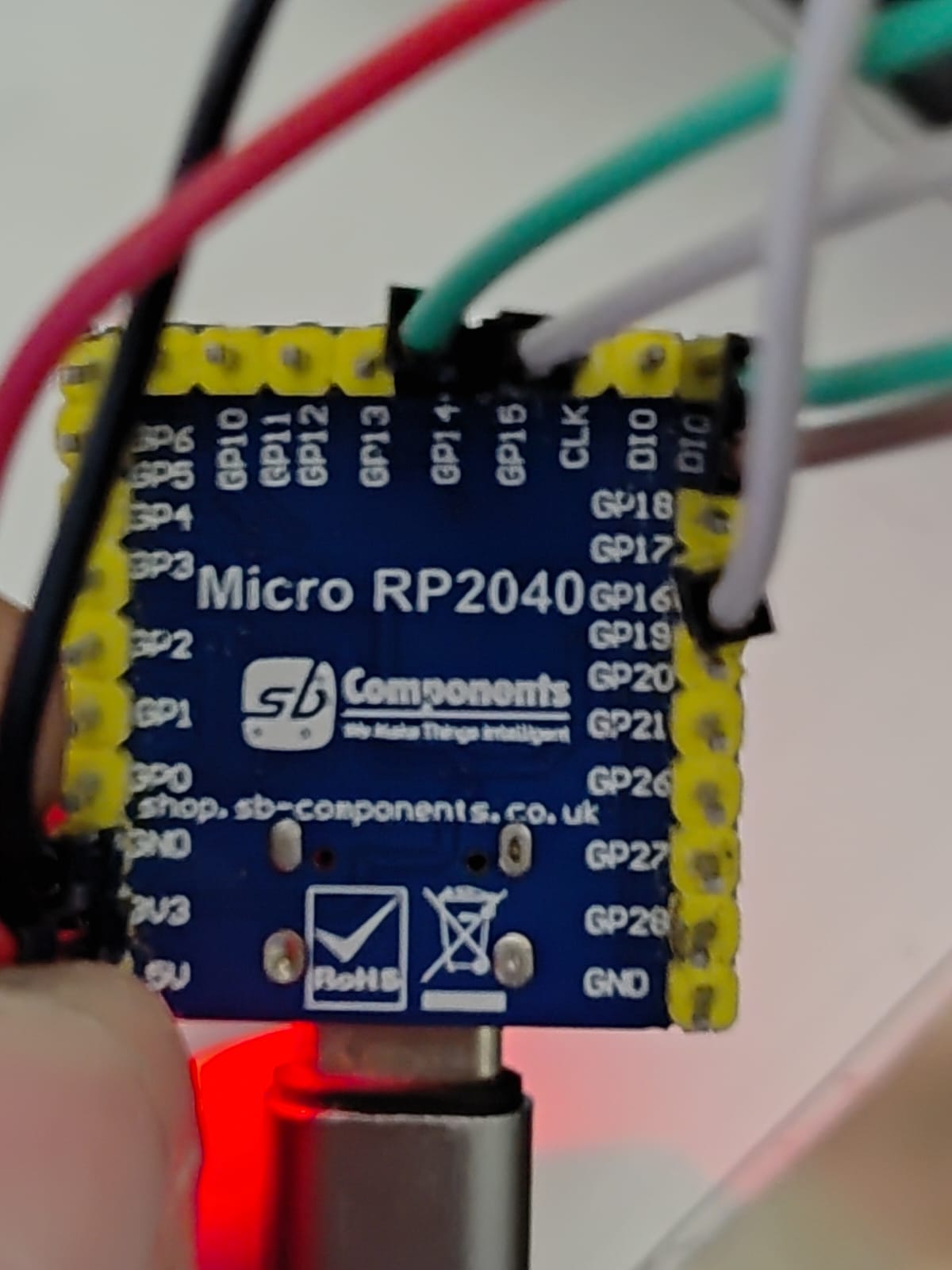
With the RP2040 connected and turned on all I get is

My connections to the RP2040 Micro board

TFT Display Pin RP2040 Pin
TFT_CS GPIO 17
TFT_RST GPIO 16
TFT_DC GPIO 15
TFT_SDA (MOSI) GPIO 19
TFT_SCK GPIO 18
TFT_VCC 3.3V
LED 3.3V
TFT_GND GND

I'm doing this pinout with all the pins except VCC and GND (cause VCC has a 3.3v that I can connect to) going through a 10k resistor to the board.

I tried with TFT_eSPI library and I wasn't even able to get it running with the ESP32... neither the RP2040 Micro board worked.

Although TFT_eSPI is the right library for RP2040 based board, it did not work..

Code I'm using for drawing the spiderweb using the ESP32 -

#include <Adafruit_GFX.h>
#include <Adafruit_ST7789.h>
#include <SPI.h>

#define TFT_DC 2
#define TFT_CS 15
#define TFT_MOSI 23
#define TFT_CLK 18
#define TFT_RST 4
#define TFT_MISO 19

Adafruit_ST7789 tft = Adafruit_ST7789(TFT_CS, TFT_DC, TFT_MOSI, TFT_CLK, TFT_RST);

void setup() {
  Serial.begin(9600);
  tft.init(240, 320);
  tft.fillScreen(ST77XX_BLACK);
  drawPattern();
}

void loop() {
}

void drawPattern() {
  int centerX = tft.width() / 2;
  int centerY = tft.height() / 2;

  for (int radius = 10; radius <= 120; radius += 10) {
    uint16_t color = (radius / 10) % 2 == 0 ? ST77XX_BLUE : ST77XX_CYAN;
    tft.drawCircle(centerX, centerY, radius, color);
  }

  for (int angle = 0; angle < 360; angle += 15) {
    float radians = angle * 3.14159 / 180;
    int x1 = centerX;
    int y1 = centerY;
    int x2 = centerX + 120 * cos(radians);
    int y2 = centerY + 120 * sin(radians);
    uint16_t color = (angle / 15) % 2 == 0 ? ST77XX_RED : ST77XX_YELLOW;
    tft.drawLine(x1, y1, x2, y2, color);
  }

  tft.fillCircle(centerX, centerY, 10, ST77XX_GREEN);
}

This worked with the ESP32 but when I changed the pin numbers so that I could connect it to the RP2040 Micro board it did not work with the RP2040.

Also with the ESP32, all the colors are inverted, but that's another issue I can fix myself.

Please help, thank you.

what exactly should the resistor do?

I heard on this forum you can connect the data pins (they are 3.3v logic) to 5v boards by using resistors as voltage level shifters if you don't have that circuitry in the display itself.

that is wrong. but RP2040 is a 3.3 V MCU. how do you have 5 V pin on a RP2040 board?

Just tried it without the resistors, same issues. I thought this board was having 5V logic because it has a 5V power output too (like the arduino UNO.. 5V logic but has a 3.3V output too)

the link to the display in post 1 looks like a TFT LCD 2.8″ 240×320 RGB SPI Display with Touchscreen ILI9341 controller with SPI interface
when using e_SPI library I would think you need to edit C:\Users\bb\Documents\Arduino\libraries\TFT_eSPI\User_Setups\User_Setup_Select.h and uncomment the line

#include <User_Setups/Setup60_RP2040_ILI9341.h>              // Setup file for RP2040 with SPI ILI9341

and check the pin definitions match your setup

Yes, I have tried this. It didn't give anything but the white display. Overall the TFT_eSPI library didn't work well for me, I used both Setup 60 and 61.

From that forum thread I attached in the first post I think the listing of the display is wrong and it is a ST7789 and not ILI9341. Adafruit ILI9341 library didn't fill whole screen, but Adafruit's ST7789 library worked perfectly.

if the Adafruit ST7789 library worked OK with the RP2040 which pins did you use?

I modified your code slightly and it works in my basement. I defaulted the clock and data pins, specified SPI_MODE2 and changed to the 240x240 device that I have. I also used a pin to turn on the backlight.

#include <Adafruit_GFX.h>
#include <Adafruit_ST7789.h>
#include <SPI.h>

#define TFT_DC 15
#define TFT_CS 17
//#define TFT_MOSI 19
//#define TFT_CLK 18
#define TFT_RST 16
#define TFT_BLK 20


//Adafruit_ST7789 tft = Adafruit_ST7789(TFT_CS, TFT_DC, TFT_MOSI, TFT_CLK, TFT_RST);

Adafruit_ST7789 tft = Adafruit_ST7789(TFT_CS, TFT_DC,TFT_RST);

void setup() {
  Serial.begin(9600);
  pinMode(TFT_BLK,OUTPUT);
  digitalWrite(TFT_BLK,HIGH);
  
  tft.init(240, 240, SPI_MODE2);    // Init ST7789 display 240x240 pixel  
//tft.init(240, 320);
 
  tft.fillScreen(ST77XX_BLACK);
  drawPattern();
}

void loop() {
}

void drawPattern() {
  int centerX = tft.width() / 2;
  int centerY = tft.height() / 2;

  for (int radius = 10; radius <= 120; radius += 10) {
    uint16_t color = (radius / 10) % 2 == 0 ? ST77XX_BLUE : ST77XX_CYAN;
    tft.drawCircle(centerX, centerY, radius, color);
  }

  for (int angle = 0; angle < 360; angle += 15) {
    float radians = angle * 3.14159 / 180;
    int x1 = centerX;
    int y1 = centerY;
    int x2 = centerX + 120 * cos(radians);
    int y2 = centerY + 120 * sin(radians);
    uint16_t color = (angle / 15) % 2 == 0 ? ST77XX_RED : ST77XX_YELLOW;
    tft.drawLine(x1, y1, x2, y2, color);
  }

  tft.fillCircle(centerX, centerY, 10, ST77XX_GREEN);
}

checked RP2040 SPI pins using the ILI9341 display
the Adafruit ILI9341_Adafruit_graphicstest.ino worked with

// RP2040 connections
#define TFT_CS    17 
#define TFT_DC    15
#define TFT_MOSI  19
#define TFT_CLK   18
#define TFT_RST   14
#define TFT_MISO  16

and TFT_eSPI library worked with

// in file TFT_eSPI/User_Setup_Select.h uncomment the following statement
//#include <User_Setups/Setup60_RP2040_ILI9341.h>              // Setup file for RP2040 with SPI ILI9341

// EDIT file TFT_eSPI/User_Setups/Setup60_RP2040_ILI9341.h check the pin definitionss are correct for the board
// #define ILI9341_DRIVER
//
// you need to change TFT_MOSI etc to suit the RP2040 pins used to connect to the display
//#define TFT_MISO  16
//#define TFT_MOSI  19
//#define TFT_SCLK  18
//#define TFT_CS   17  // Chip select control pin
//#define TFT_DC   15  // Data Command control pin
//#define TFT_RST  14  // Reset pin (could connect to Arduino RESET pin)
// RP2040 VBUS (5volt) to display VCC if J1 is open

for the ST7789 display in file TFT_eSPI/User_Setups/Setup60_RP2040_ILI9341.h try uncommenting line (comment out any other drivers)

#define ST7789_DRIVER      // Full configuration option, define additional parameters below for this display

and define the SPI pins etc

TFT_eSPI test code

// RP2040 TFT_eSPI library  example TFT_Print_Test

// in file TFT_eSPI/User_Setup_Select.h uncomment the following statement
//#include <User_Setups/Setup60_RP2040_ILI9341.h>              // Setup file for RP2040 with SPI ILI9341

// EDIT file TFT_eSPI/User_Setups/Setup60_RP2040_ILI9341.h check the pin definitionss are correct for the board
// #define ILI9341_DRIVER
//
// you need to change TFT_MOSI etc to suit the RP2040 pins used to connect to the display
//#define TFT_MISO  16
//#define TFT_MOSI  19
//#define TFT_SCLK  18
//#define TFT_CS   17  // Chip select control pin
//#define TFT_DC   15  // Data Command control pin
//#define TFT_RST  14  // Reset pin (could connect to Arduino RESET pin)
// RP2040 VBUS (5volt) to display VCC if J1 is open

/*  
 Test the tft.print() viz. the libraries embedded write() function

 This sketch used font 2, 4, 7
 
 Make sure all the required fonts are loaded by editing the
 User_Setup.h file in the TFT_eSPI library folder.

  #########################################################################
  ###### DON'T FORGET TO UPDATE THE User_Setup.h FILE IN THE LIBRARY ######
  #########################################################################
 */

#include <SPI.h>

#include <TFT_eSPI.h> // Hardware-specific library

TFT_eSPI tft = TFT_eSPI();       // Invoke custom library

#define TFT_GREY 0x5AEB // New colour


void setup(void) {
  tft.init();
  tft.setRotation(2);
}

void loop() {
  
  // Fill screen with random colour so we can see the effect of printing with and without 
  // a background colour defined
  tft.fillScreen(random(0xFFFF));
  
  // Set "cursor" at top left corner of display (0,0) and select font 2
  // (cursor will move to next line automatically during printing with 'tft.println'
  //  or stay on the line is there is room for the text with tft.print)
  tft.setCursor(0, 0, 2);
  // Set the font colour to be white with a black background, set text size multiplier to 1
  tft.setTextColor(TFT_WHITE,TFT_BLACK);  tft.setTextSize(1);
  // We can now plot text on screen using the "print" class
  tft.println("Hello World!");
  
  // Set the font colour to be yellow with no background, set to font 7
  tft.setTextColor(TFT_YELLOW); tft.setTextFont(7);
  tft.println(1234.56);
  
  // Set the font colour to be red with black background, set to font 4
  tft.setTextColor(TFT_RED,TFT_BLACK);    tft.setTextFont(4);
  tft.println((long)3735928559, HEX); // Should print DEADBEEF

  // Set the font colour to be green with black background, set to font 4
  tft.setTextColor(TFT_GREEN,TFT_BLACK);
  tft.setTextFont(4);
  tft.println("Groop");
  tft.println("I implore thee,");

  // Change to font 2
  tft.setTextFont(2);
  tft.println(F("my foonting turlingdromes.")); // Can store strings in FLASH to save RAM
  tft.println("And hooptiously drangle me");
  tft.println("with crinkly bindlewurdles,");
  // This next line is deliberately made too long for the display width to test
  // automatic text wrapping onto the next line
  tft.println("Or I will rend thee in the gobberwarts with my blurglecruncheon, see if I don't!");
  
  // Test some print formatting functions
  float fnumber = 123.45;
   // Set the font colour to be blue with no background, set to font 4
  tft.setTextColor(TFT_BLUE);    tft.setTextFont(4);
  tft.print("Float = "); tft.println(fnumber);           // Print floating point number
  tft.print("Binary = "); tft.println((int)fnumber, BIN); // Print as integer value in binary
  tft.print("Hexadecimal = "); tft.println((int)fnumber, HEX); // Print as integer number in Hexadecimal
  delay(10000);
}

Hi, @oldcurmudgeon, what is the pinout I need to use for this SPI_MODE2?

Also, it seems with @horace there may have been a misunderstanding, till now I have not been able to get the display working with my RP2040 board.

I got the display working properly with the ST7789 library with the ESP32.

Now I have gotten these two answers to the question and I'll be trying both of them.

at least you know the RO2040 pins which worked on the tests @oldcurmudgeon and I ran which should give you a start

How would I know what @oldcurmudgeon has used, he has said he defaulted the pins, what's the default I can't find.

I would assume the SPI0 defaults


in code

//#define TFT_MISO  16
//#define TFT_MOSI  19
//#define TFT_SCLK  18
//#define TFT_CS   17  // Chip select control pin

1 Like

I tried both codes and both of them show the same thing. The white screen and nothing else. I'm really frustrated with this board because it all works so well with the ESP32.

With the code from @horace, the backlight blinks every 8 seconds or so. With the code from @oldcurmudgeon it does nothing but show the white screen.

what pin have you connected it too? I usually connect to 3.3V supply

I don't have a ST7789 so am running out of ideas

Clock and data are still 19 and 18, you just don't specify them on the constructor. Usually the pins are specified if you are using software SPI rather than hardware. This was a critical difference, apparently specifying the pins causes it to to try to do software SPI on the hardware pins.

The SPI interface can have various combinations of clock and data.

My display uses mode 2. This can be specified on the tft interface and is passed on the SPI commands.

I used a actual PI Pico and a 7 pin variant of the display. I put the back light on a pin because I was too lazy to get out a breadboard and more jumpers to connect it to 3.3V :slightly_smiling_face:.

Did you actually try my code?

Yeah I did, I'm very desperate to get this working I'll run all the code I get.

I tried all Mode 0 Mode 1 and Mode 2 but none of them worked...

I think this is the issue. Does my board not support this at all?

Currently using this code (Ignore the connected pins in that pic, it's an old pic)

#include <Adafruit_GFX.h>
#include <Adafruit_ST7789.h>
#include <SPI.h>

#define TFT_DC 15
#define TFT_CS 17
//#define TFT_MOSI 19
//#define TFT_CLK 18
#define TFT_RST 26
#define TFT_BLK 20


//Adafruit_ST7789 tft = Adafruit_ST7789(TFT_CS, TFT_DC, TFT_MOSI, TFT_CLK, TFT_RST);

Adafruit_ST7789 tft = Adafruit_ST7789(TFT_CS, TFT_DC,TFT_RST);

void setup() {
  Serial.begin(9600);
  pinMode(TFT_BLK,OUTPUT);
  digitalWrite(TFT_BLK,HIGH);
  
  tft.init(240, 320, SPI_MODE0);    // Init ST7789 display 240x240 pixel  
//tft.init(240, 320);
 
  tft.fillScreen(ST77XX_BLACK);
  drawPattern();
}

void loop() {
}

void drawPattern() {
  int centerX = tft.width() / 2;
  int centerY = tft.height() / 2;

  for (int radius = 10; radius <= 120; radius += 10) {
    uint16_t color = (radius / 10) % 2 == 0 ? ST77XX_BLUE : ST77XX_CYAN;
    tft.drawCircle(centerX, centerY, radius, color);
  }

  for (int angle = 0; angle < 360; angle += 15) {
    float radians = angle * 3.14159 / 180;
    int x1 = centerX;
    int y1 = centerY;
    int x2 = centerX + 120 * cos(radians);
    int y2 = centerY + 120 * sin(radians);
    uint16_t color = (angle / 15) % 2 == 0 ? ST77XX_RED : ST77XX_YELLOW;
    tft.drawLine(x1, y1, x2, y2, color);
  }

  tft.fillCircle(centerX, centerY, 10, ST77XX_GREEN);
}

I've connected it properly but still only a white screen to be seen

Is this of any help?

image

and there's this written on their github page

Update: Managed to get it working. It was indeed this printing mistake on the board...

image

@oldcurmudgeon provided me with the code that is working right now.

Thank you for saving my project from my deadline!

From the github picture and comment it appears that the numbering on the board has pins 16 and 18 reversed. Have you tried reversing them on your connections?

1 Like