I like many have fallen in love with silicone wire.
I recently purchased a low cost Logic Analyzer (which works great). The inputs were a simple set of 10 male pins.
I wanted to make silicone leads but didn't want the difficult to insert standard duPont connectors.
So I took #28 silicone wire, laid then in what I think is a pretty standard color/channel pattern.
I taped the wires together (temporarily).
Then I inserted them into a good quality amp IDC 10 pin connector. Squeezed it shut in a vice, tested and viola I have a very flexible set of logic test leads.
These colors match Saleae color "code" as I also have an old Saleae Logic.
What made me happy was how well they work in the IDC connector
It may only be 16 strands but its as limp as cooked pasta (al dente). And its much better than the duPont jumper wires. I use the #28 for everything but power, then I go to #26 (or maybe #24). All my runs are relatively short so the wire resistance is trivial and I can leave a small PCB on the bench without the wire taking "it away".
IMHO PVC wire is so "yesterday"
UPDATE: The IDC connector I used was a TE (aka AMP) 1658620-1 (10 position)
This is a great find. I don't need any more wire at the moment but I'll remember to look on Amazon next time. I had been purchasing silicone wire from ebay vendors.
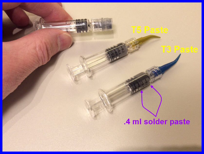
Hi, I'm looking for a suggestion on soldering 7 SOT-223 Fets. I have a "hot plate" that I've used in the past but my issue was getting the solder on the pad area. I was thinking of spreading the solder past on a flat surface at some thickness. Then using the Fet like an ink stamp to pick up some solder.
inspired by Larry's holding device but not having any big magnets on hand
i made these on the 3d printer for 10mm and or 3mm magnets
with a m5 thread up the middle and a 2mm spoke hole
I have a HX711 load cell board. As I monitor it with no weight I see the value varying nearly every reading. So to get a better feel of what is going on I wanted to capture the serial output over a long time.
The IDE 2 serial monitor is not so good for a lot of readings.
Putty seems to hold all data until you close then writes to a file. I haven't looked into the actual operation of putty logging but it was enough to make me uncomfortable.
So I looked into the old MS-DOS command line commands. Now usable in the command prompt window. It tuned out to be exceedingly simple.
>c:\windows\system32\ type com3: >> data.log
It must be run from the system32 folder else the type command can't find the com port.
Now if your like me you have used many serial ports with different Arduino's etc and you are in the com10 and above. It seems the old DOS commands don't like 2 digit com ports. For that I found "ComNameArbiterTool.zip". It allows you to "reset" the com port numbers so they can be reused.
I don't know.... it is a tip. I couldn't decide on what category might be better. If you have a suggestion please let me know and I'll ask the moderator to move it