withstands soldering temperatures, and can be used to hold components in place when you're doing evil things like expecting the solder to provide mechanical integrity (say, soldering header pins flat agains a board.)
(It's a pretty substantial-size package, especially since it's mostly re-usable. Unfortunately, smaller batches of silicone putties that I tried (ie "Silly Putty" are NOT capable of sustaining the same heat.)
boolean (8 bit) - simple logical true/false, Arduino does not use single bits for bool
byte (8 bit) - unsigned number from 0 to 255
char (8 bit) - signed number from -128 to 127. The compiler will attempt to interpret this data type as a character in some circumstances, which may yield unexpected results
unsigned char (8 bit) - same as 'byte'; if this is what you're after, you should use 'byte' instead, for reasons of clarity
word (16 bit) - unsigned number from 0 to 65535
unsigned int (16 bit)- the same as 'word'. Use 'word' instead for clarity and brevity
int (16 bit) - signed number from -32768 to 32767. This is most commonly what you see used for general purpose variables in Arduino example code provided with the IDE
unsigned long (32 bit) - unsigned number from 0 to 4,294,967,295. The most common usage of this is to store the result of the millis() function, which returns the number of milliseconds the current code has been running
long (32 bit) - signed number from -2,147,483,648 to 2,147,483,647
float (32 bit) - signed number from -3.4028235E38 to 3.4028235E38. Floating point on the Arduino is not native; the compiler has to jump through hoops to make it work. If you can avoid it, you should. We'll touch on this later. Sparkfun.
You select the 'type' best suited for your variables.
ex:
your variable does not change and it defines a pin on the Arduino. const byte limitSwitchPin = 34;
since an analog variable can be 0 to 1023, a byte will not do, you can select 'int'. int temperature;
if your variable needs to be within -64 to +64 a 'char' will do nicely. char joystick;
if your variable is used for ASCII then you need type 'char', char myText[ ] = "Raspberry Pie Smells";
if your variable enables some code then boolean can be used. boolean enableFlag = false;
millis() returns the time in ms since rebooting, unsigned long currentTime = millis();
etc.
Use a switch connecting the RESET pin to the GND pin. Now, if you want to turn the Arduino off without unplugging in or cutting power to components, flip the switch!
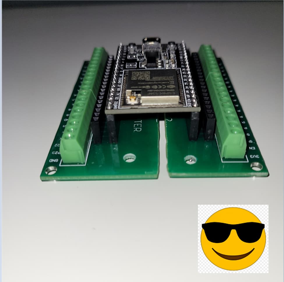
If you happen to order a terminal shield which is the wrong width for your ESP32 board, because everyone's favorite Asian Ecommerce site never provides an adequate description, then you can get a heavy-duty razor blade (cheap box cutters probs won’t work), score the board down the middle a few dozen times, then snap it apart with your hands. I used a narrow piece of flat bar to line up the first few scores. Finish it off with a file and sandpaper when done. Also drill additional mounting holes if you like. I Then cleaned all the dust away with some IPA and a brush. soapy water might be fine too.
I then experimented with applying a thin coat of 2-part epoxy adhesive to all the edges, using both my gloved fingers and a cotton swab. This worked great in sealing up all the nasty fiber's which may have been left in my machining process, and gave the added benefit of a silky-smooth corner finish, which is actually way nicer to handle than any other pcb component I've purchased
Hi,
I have had a similar situation when making a test jig for a product, my boss simply got the angle grinder out with a cutting disk and did the same thing.
Yes PPE was worn, and we used a couple of layers of conformal spray to fix the cut edges.
Luckily the particular PCB composite used for the shield cut very easily. I've had some trouble hand cutting and drilling some other boards. Thanks for alerting me about that conformal spray.
If you want the result to be a board, not two, then just epoxy a stiff material across the gap. Maybe a piece of PCB, or a piece of other sheet goods. Result is a card that may not be as rigid as the original, but can still be mounted on the corner standoffs quite acceptably.
C
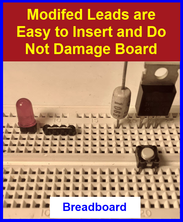
Over sized flat component leads can be difficult to plug into solderless breadboards.
These oversized leads can even damage the springs in the breadboard conductors.
It takes only a few seconds to modify these component leads so they can be accommodated better.
Flat leads are bent at 90 degrees, so their orientation lines up with the breadboard spring mechanism.
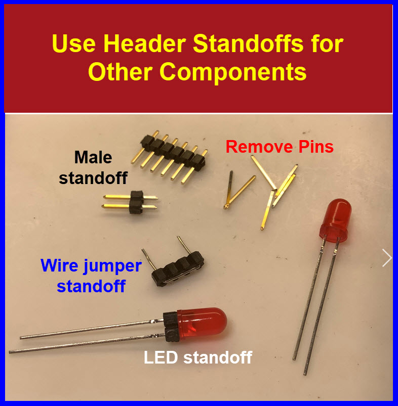
Use the plastic standoffs from male headers on other components to stabilize them and lift the component off the PCB surface.
Pull the male header pins out of the standoffs, insert the new component leads in the plastic standoff holes.
I've found neodymium magnets attached to walls or your work bench or wherever you make your projects at is extremely convenient, I almost exclusively use it, it's great for any tool with at least a small section of metal, which is almost every tool. If your magnet is neodymium, the tools (I'm assuming nobody here would try to put anything other than small - medium hand tools on it ), and it's very easy to just pull it off with minimal force and reattach it hanging, which uses space that would be hard to utilize otherwise and frankly is kinda cool.
I have a pair with super sharp tips. For the most part they hang on the wire/test rack. I only need them for some SMD measurements. The day to day probes are pretty dull.


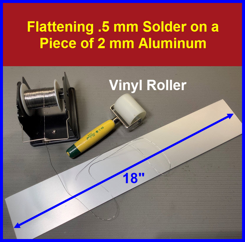


 Hot Air Mini Wave Soldering")


")