Share tips you have come across

Fixture Plate #2

Further to post #921.

Forgot to add to the above link, better late than never.

The Fixture Plate Is also very useful as a hardware development tool.

Attached are a number of images showing how flexible the plate can be when used with standard sized modules; the combination can speed in your hardware project setups.

All components are securely held in place and the whole setup can easily be moved to different locations.

If there are any question with the images, please ask for explanations.


Hints

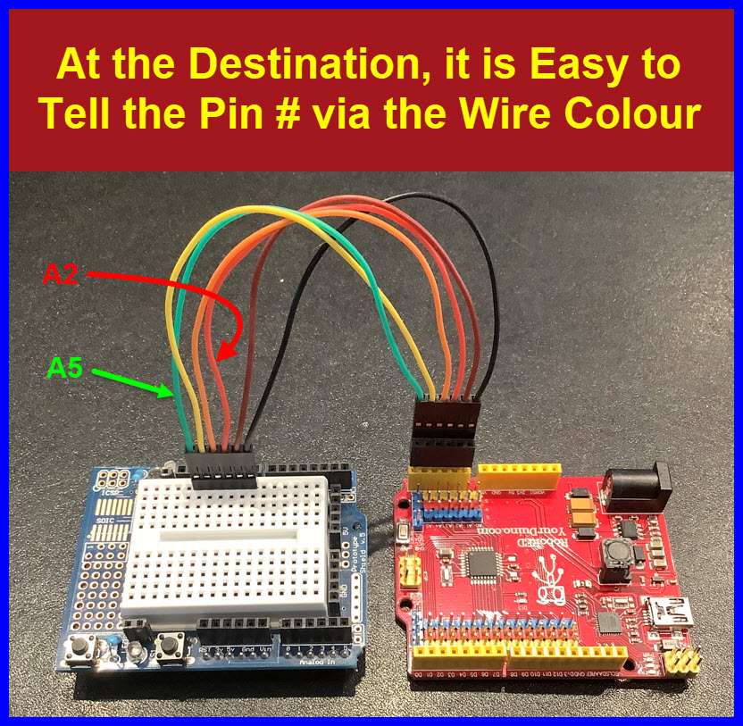
Prewire Arduino I/O pins to colour coded Breadboard headers.

See this post for oscilloscope probe connection modules.

Further to Post #940


  • The blind screw in the above post can rotate when the brass standoff is tightened.

The following images show how to modify the flat headed screw to prevent the screw from rotating.

Here is a pretty neat one.

I like these tiny 2.54mm screw terminal blocks, as you can have them replace standard 2.54mm header pins on many components, in order to create some very strong and reliable connections for single core jumper wire, and/or male dupont connectors.

You can also cut some double-sided header pins, screw one end of the headers into the terminal blocks and make your components breadboardable again :grin:

Oscilloscope Connections on a Solderless Breadboard

Whenever you try to look at a signal on a solderless breadboard, the slightest probe movement inevitably pulls out the wire or component to which it is attached.

The following images show how to make a sturdy termination module where the scope probe can be attached.

  • The scope GND clip is attached to a similar module.

The module is made from a 2X5 pin, male, wire wrap header.

The 10 pins in this module ensure the probe will not dislodge a wire or a component.

Locking Knipex Pliers

Add an elastic to my favourite pliers makes them even more flexible.

Save Time, Mark Breadboard Component Leads

I cannot remember how many times I’ve looked up component footprint leads.

Save the stripping form silicone insulated wire to identify the power and signal leads of breadboard components.

Hi,
I do the same thing when building toriodal matching and balance/unbalance RF transformers.

Tom... :smiley: :+1: :coffee: :australia:

A sharpie allows easy marking on card edge, red V, n
black G and whats left is signal. For more than one signal line i break out V and G and band both with on piece of hs tubing and then the G lead with a smaller dia piece of hs as a polarity indicator.

Maybe not my best contribution, But I made two simple holders for my two multimeters today. I just used plastic pipes, som wood and hot glue.

It was nice to have a little extra space on the bench.

Going vertical is often overlooked by people.

:+1:

Dupont Connector Crimping

This was covered a while back and is now duplicated here.


My favourite crimper is:
Platinum Tools 16801C Open Barrel Contact Crimp Tool Clamshell


These are what I use with percentage of times I use them:

First crimp the conductor

Finally crimp the insulation

You might have to remove some insulation with flush nippy cutters and tune the crimp shape with needle nose.


The Platinum Tools 16801C Open Barrel Contact Crimp Tool Clamshell IMO is the best.
≈ $30.00


When using the 16801C, after crimping the "insulation" on the largest size, I finish with a very light final crimp on the smallest size.

Double over the conductors on 26 and 28 AWG wires.


I mostly use silicone insulation wire with high strand count; 28 AWG has sixteen 40AWG strands.

Silicone insulated wires as mentioned

  • 28AWG 16 strands
  • 24AWG 40 strands
  • 20AWG 100 strands

Breadboard friendly display module based around the AT Mega4809 (as used in Nano Every). Shown is the serial display, which is displaying millis from a Nano Every. Also can show serial data as hex. There are 8 digital inputs, which can be displayed as simulated LEDs or a simple trace like a logic analyser. The display can be rotated to suit the orientation of the breadboard. There are 2 analogue inputs, but I've not written any code for them yet. There are 2 serial ports, one on the breadboard connector and one on the UPDI connector.

Programming was with this UPDI programmer:

and was written using:

The display is this one:

PCB files are KiCAD

LogicAndSerial128x128V2.zip (15.6 KB)

Logic level indicator.zip (130.5 KB)

Cutting Shield for Your Workroom Floor

You may have experienced a bit of feedback about small cuttings on your work room floor.
:shushing_face:

When cutting items on your Bench Pin, discussed much earlier, small wires, header pins and plastic often fall on the floor.

Make a shield to keep these small cuttings from getting into the vacuum.

The key component in this tip is the 2 Fence clamps (Bessey Table Clamps) that keep the shield components together.

You can buy these clamps, two for $10.00.

EDIT

Also, if you add a piece of plywood on top of the cloth shield (clamped in place) you can extend your work bench surface area.

Commonly Used Components

It seems like we search for commonly used components over and over again.

Add a removable clear plastic Component Cup to your prototyping jig so they are always at hand.

EDIT, Magnets are better :nerd_face:

Ultrasonic Reflector For Your Development Jig

Make life a bit easier by mounting a SR04 Ultrasonic Distance sensor on a semi rigid platform.

A 20cm, M2 threaded rod and associated reflector makes for easy testing in your project sketches.

General project build guidelines:
arduino-construction-notes.pdf (7.0 MB)


Convert a Stand-Off from One Thread Type to Another

If you have a selection of threaded brass inserts, use these to modify an existing stand-off thread.

The following images show the easy process.

Simply compress the brass insert into the stand-off hole.

You may have to enlarge the hole to accept the brass insert.

You can also heat insert using a soldering iron.

BTW

Old Bic pens make nice stand-offs; add a brass insert to these too.