I post this only that it might aid someone else.
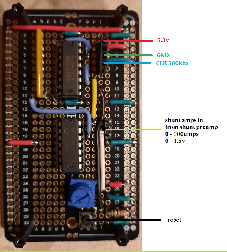
I designed this circuit so I could keep track of the peak discharge current for each of my 4 battery banks. It is designed around my unique system. My system has a 60 amp charge controller, 2ea 6000 watt inverters and 4ea 48v FLA battery banks. Each bank has it's own 100a 75mv shunt. That shunt voltage is amplified by separate LM324 op amps. The 5.3 v supply is a adjusted 78L05 regulator running of my existing 48v to 12v supply. It is 5.3v to give enough overhead to obtain 4.5v peak from the LM324s.
The R-2R network appears to be the peak detector, nice job. I see two potential problems, one you cannot run much current through your prototype board, it will fry. The 100A shunt needs to be external.
I cannot follow the 5.3V if it is being sourced from the 12V pr the 48V, hopefully the 12V.
Nice for small currents, not for 0 - 100amps. Also, to determine the peak for (say the last 24hrs) would require constant MCU monitoring. My circuit is a hardware approach that only requires mcu to check it once per day.
The INA226 (15-bit resolution) would even be a better choice.
Those chips are designed to be used with a 75mV shunt (any current).
The fact that most boards have a built-in 0.1Ohm/3.2A shunt shouldn't stop you from removing it and using an external 75mV/100A shunt.
The LM324 has a high input offset and drift, so is not suitable to measure low currents.
Leo..
Interesting. For peak purposes it would require continual MCU monitoring. My configuration does not.
However, it may serve a useful purpose for me if I could combine 4 shunt inputs. Could that be done with a simple resistor network or (as I suspect) I would need an OP amp to do it.
I have attached a circuit which appears valid. Having never dealt with the INA226, I would appreciate your input.
This is a solar environment so all inputs would be either positive or negative. Discharge currents would yield positive shunt voltages.
Expected discharge voltages would be less than +75mv.
Expected charge voltages would be less than -18.75v.
I think OP has a 48volt setup.
The INA226 has an external VBus input if voltage measurement is also required, the 3221 has not. Up to 16 INA226 boards can directly be used on the same I2C bus.
The shunt must be low-side, because of the 36volt common-mode voltage limitation of the INA226. But even then, the INA226 can measure bi-directional (-75mV). The LM324 can not.
Leo..
Let me clarify my goal here. The info I require is.
peak discharge current values for each of 4 battery banks. Sampled once per day. My peak detector and one ADS1115 will accomplish this.
I do not require individual bank charge and discharge currents.
I do require total bank charge and discharge currents. Two 4 input op-amps and 1/2 of an ads1115 should accomplish that.
The total bank charge current would be sampled no more often than once every 10-15 minutes. this value would be used to determine a fully charged total battery bank.
A full charged FLA battery bank is defined as a stabilized float current. This would be roughly 2ma per AH capacity (dependent on battery age and condition). Therefore for my 4 bank 48v system, I would have to discriminate approx 2-5 amps of total charge current.
Just note that your choosen opamp is a poor choice for low voltages (low shunt currents).
The offset of an LM324 is stated in mV, the INA226 in uV, 1000 times better.
The A/D range of an ADS1115 is 256mV, the INA226 is 82mV, 3 times better.
Leo..
Understand that I must derive an analog signal to run the peak detector. Doing digital peak detection would require 24/7 MCU time. Analog peak detection allows the MCU to query the result once per day.
Right now I am pondering how to compensate an OP amp for the parasitic resistance (and probable changes to that resistance) between the individual shunts and the buss bar.
The INA226 looks like an excellent unit but I don't think it fits in this application as I already need an pre-amp.
I understand that you need to monitor 24/7 for a peak detector.
I don't understand yet why you want a peak detector.
What use would that be on the load of a solar system.
Cumulative draw sounds moresensible to me.
Just note that an ADS1115 can't work with negative voltages (not even in differential mode).
The shunt must deliver a positive voltage on battery discharge.
Or your opamp front-end must be able to.
Leo..
I now understand why.
But why measure peak currents. An increased Ri of a bank should show up at any current.
Charge and discharge.
you could just compare the four accumulated charge and discharge currents.
That could also measure self-discharge of each bank.
Leo..