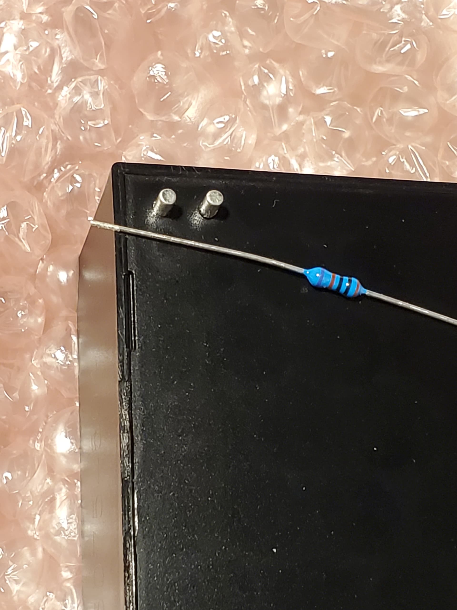
Looking for suggestions on how to solder these 0.08 inch diameter pins (2 mm) to a pcb.
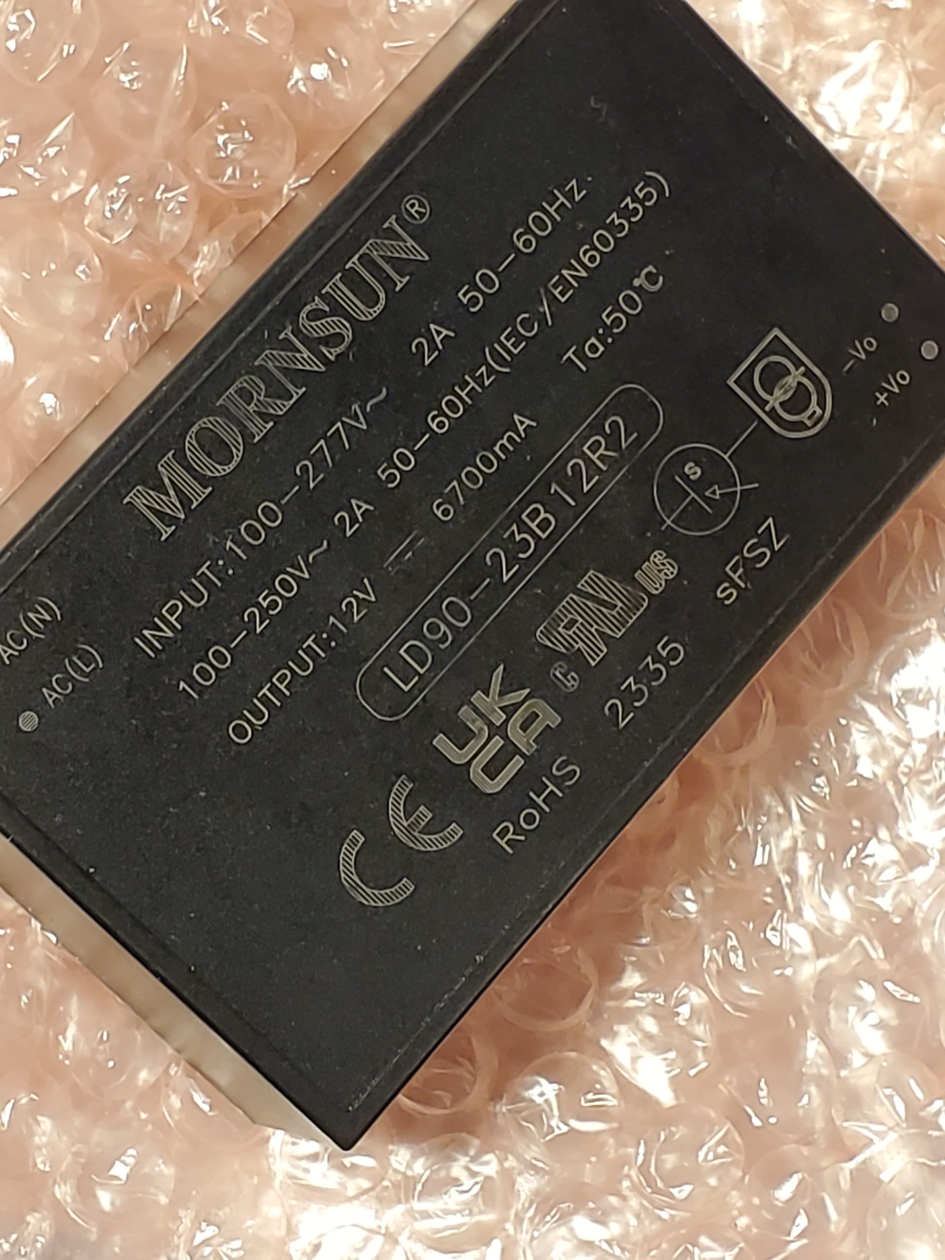
The device datasheet says temperature limit is 360 deg C for 3 to 5 sec.
I have a Sparkfun 937b 60 w soldering station.
Resistor included for size reference.
I was thinking of using the largest tip I have, cranking the temperature up to the max (480 deg C), tinning the tip, and holding the iron against the end of the pin, holding the solder against the side of the pin at pcb interface, and removing the iron as soon as the solder flows.
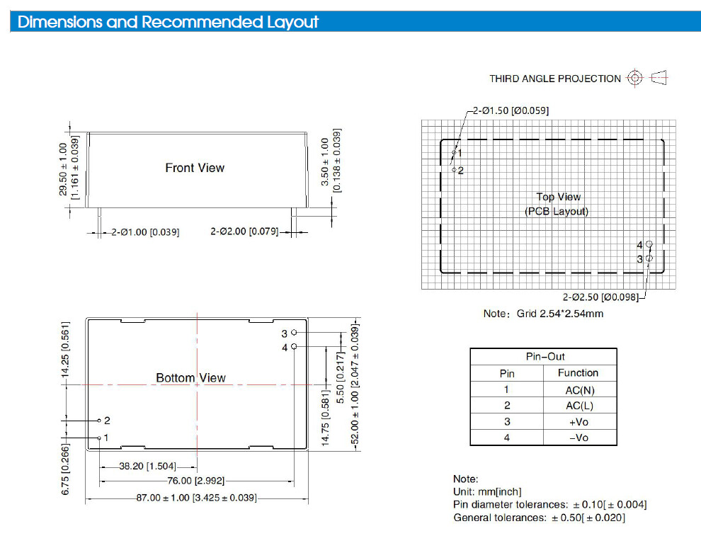
Do they just set on the pc board? Or do they fit into holes in the board? Either way, heat and tin the pins with solder. Then heat and tin where you want to put them. Finally hold the pins on the tinned place and heat with your iron until the solder that is there melts and then let the pins cool.
When we encountered something like that in the assembly service, the pins were knurled and pressed into the hole in the printed circuit board. THEN both were soldered.
That will not tin the tip, it will coat the tip in over cooked solder.
365C should be enough, higher temperature can degrade the solder.
Can you please post some pictures with the PCB mount power supply fitted BUT not soldered into your PCB.
So we can see the area that you are aiming to solder.
There is a different version that has screw terminals - see the LD90-23B12R2 datasheet.
The datasheet gives you the recommended soldering temperature, as DaveEvans mentioned in his original post.
[soapbox] Place the hot tip on the join, count to 3, (3 seconds), then apply the solder, count to 2 (2 Seconds) pull the solder away, pull the iron tip away. Here endeth the lesson.
[/soapbox]
You 60W iron will be sufficient, keep the tip clean.
DONE in 5 Seconds. 5 seconds is a long time.
You will not do any damage if you take 6 or 7 seconds, believe me.
If joint looks bad, let it cool down and try again.