What I am trying to do
I am trying to build a circuit so that you can hit a button to turn a microcontroller on (I am using an Uno board), but hitting the button again does not turn it off. Instead, I wan't to have it turned off by the microcontroller deciding it should turn itself off. This is connected to a battery, so I want this to have the device completely power off when not in use without needing to disconnect the battery.
Essentially, I want to have it turned on by hardware, but off by software.
What I have done to implement this
In order to implement this I decided to make a power circuit where the power from the battery would flow to the board by one of two ways:
-
a button
-
a transistor, which is controlled by digital pin on the microcontroller
The transistor that I used for experimenting with this circuit is an N-channel power MOSFET transistor, that I got from Adafruit here: N-channel power MOSFET [30V / 60A] : ID 355 : $2.25 : Adafruit Industries, Unique & fun DIY electronics and kits. I know this transistor is way over kill for this project, but it was what I had on hand. I don't suspect the type of transistor is what is causing my problem.
The basic schematic is shown in the picture.

What I expected / did not expect
I expected to need to tie the gate of the MOSFET to the ground (I did, using a 1k resistor) to keep it normally at negative and thus off, but did not expect to need to put in resistance between the gate of the MOSFET and the pin on the Uno board that I am using to control the MOSFET. If I didn't put in the resistance, when I connected the gate to the I/O output pin the device would turn on before I pressed the button. If I connected the gate to ground rail, it would stay off, as expected. If I connected the gate to the +5 rail, the Uno would turn on, as expected.
As soon as I touched the gate to any pin on the board or to the drain of the MOSFET, the board would turn on. You can see that here:
My sort of solution
By experimentation, I found that if I put in between 1.7k and 2.2k of resistance between the gate of the MOSFET and the I/O pin I am using, I could get this to work (this is reflected in the schematic above). Too little and the board would turn on automatically (rather than after a button push) and too much and the board would not stay on (i.e. even after pushing the button the board would not stay on, largely as the HIGH on the I/O pin could not keep the MOSFET gate HIGH).
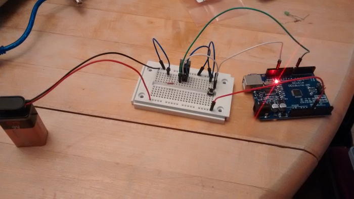
However, even with this solution the power LED on the Uno board would sometimes faintly light. Really faintly. As far as I can tell the microcontroller is not running as the Pin13LED is not on (I turn it HIGH as soon as the board starts running), but since I want this to be completely powered off, this faintly lighted LED concerns me as it indicates some power is flowing.
You can see the circuit here (with 2k of resistance between gate and I/O pin). In this circumstance the power LED is not lit up (i.e. the board remains off until I press the button, at which point it stays on as the pin is held HIGH for the MOSFET gate. Five seconds later (because that is what I decided for this test), the Uno takes the pin to LOW and the whole board powers off. I consider this to be success.

My questions
-
Why is it that connecting the MOSFET gate pin to one of the I/O pins or to the drain of the MOSFET causes the MOSFET to 'turn on' (let current flow from source to drain, not sure of the correct terminology)?
-
Is there something that connects the I/O pins on the Uno board to ground?
-
Why does putting resistance between the gate and the I/O pin help to (mostly) solve this?
-
I figured out the resistance needed by experimentation, but is there a way to calculate what this should be?
-
Is current actually not flowing if the power LED is not lit, or is it that it is flowing very slowly and can't light up the LED? The fact that the LED sometimes is very faintly lit concerns me about this. If it is flowing slowly, how much (approx) would that be and will it have a big impact on battery life?
*** My code ***
This is the code that I am using the test this circuit
int OnOffPin = 7;

void setup() {
  // initialize digital OnOffPin as an output.
  pinMode(OnOffPin, OUTPUT);

  // initialize digital pin 13 to show when the OnOffPin is high
  pinMode(13, OUTPUT);
}

void loop() {
  digitalWrite(OnOffPin, HIGH);   // turn the OnOffPin on by making the voltage HIGH
  digitalWrite(13, HIGH);
  delay(5000);                   // wait for five seconds

  digitalWrite(OnOffPin, LOW);  // turn the OnOffPin off by making the voltage LOW
  digitalWrite(13, LOW);
  delay(5000);                  // wait for five seconds, but this should never come back on
}
Many thanks in advance for helping to answer these questions.
