Hello!
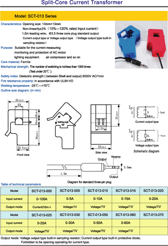
I just got one of these to play around with: Non-Invasive Current Sensor - 30A - SEN-11005 - SparkFun Electronics
I've only used one current sensor in the past and it had positive and negative jacks, so I'm a bit confused as to hook this one up. I've been looking around at various example projects but haven't found one that uses this exact clamp and show how it is hooked up.
Any ideas?
Thanks!
See the datasheet for it here:
Looks like a TRS headphone jack (tip-ring-sleeve) in which the tip and sleeve are the voltage output signal and the middle "ring" is unused.
Also this comment from the product's comments section looks relevant:
"Now i understand that Voltage/1V means that it is a voltage mode unit (has built-in current sense resistor to convert current into voltage) and 1V means that the full scale current of 30A would read 1V (apparently the burden resistor is 1v/30a = 33.33333333 milli-ohms). Could measure quite accurately using Vref = 1v with 10-bit ADC in the Arduino"
--
The Ruggeduino: compatible with Arduino UNO, 24V operation, all I/O's fused and protected
Clamp it around your wire. Put your multimeter on the two output pins.
If current is flowing only 1 direction and you want to see a positive voltage, arrange your meter pins so they read a positive voltage. Connect the meter Common lead to arduino ground, and the positive lead to an analog input pin. Make sure the resulting reading will be 5V or less.
If current can flow both directions, then you will need to offset the common lead so that the positive lead can be higher and lower, that is, varying up to +2.5V and down to -2.5V. You might be able to do that using two 10K resistors in series between +5 & GND, the junction being the meter Common and the positive lead to the analog input.
Or use a unity gain op-amp circuit to do the same, or takea advantage of the op amp to add gain if the probe output is too low.
I might have typed too slow, I think this still may apply.
