I haven't tested this yet, since I'm still waiting for my 100 LEDs to come in, but is one data-in signal for 280 LEDs fine? 140 LEDs are for the Left Channel 7 band while the other 140 LEDs are for the right channel. Can one data line control all of these or do I need another digital output? I was trying to find the specs online, but no luck.
is one data-in signal for 280 LEDs fine?
Yes it is fine.
Mike/or anyone else,
Do anyone know how to test to see if your Digital Input is flowing through all the LEDs? I cut up my LEDs strips by 20 LEDs and bought these jumpers to tie them together. Every other LED strip (Starting with the 2nd one) is flipped in order for the LEDs strips to reach. Before I cut them up, I ran my code and most of my LEDs were lighting up but for some reason this is not happening anymore. Only the first strip is working and I'm not sure how to test out the other lights. Ideas?
I've done a continuity check on the 5VDC and GND and they're good so this is why I'm saying it might be the digital input. I've also attached a picture for reference.
Ignore my comment avoid. With a little help from a friend, I have it work.
Have another question though. The following is my code just for the left handle channel which is lighting up 7 bands.
#include <MSGEQ7.h>
#include <Adafruit_NeoPixel.h>
//#define A0
//#define A1
#define pinReset 27
#define pinStrobe 26
#define LEDs 140 //total number of LEDs
#define PIN 22
#define OnColor 0x0000FF // BLUE
#define OffColor 0x000000 // OFF
int SpectrumLeft[7];
int SpectrumRight[7];
int SpectrumGraphLeft[7][20];
Adafruit_NeoPixel Strip = Adafruit_NeoPixel(LEDs, PIN, NEO_GRB + NEO_KHZ800);
//#define MSGEQ7_INTERVAL ReadsPerSecond(50)
//#define MSGEQ7_SMOOTH 191 // Range: 0-255
//CMSGEQ7<MSGEQ7_SMOOTH, pinReset, pinStrobe, pinAnalogleft> MSGEQ7;
// Choose a PWM pin!
#define pinLed 22
void setup()
{
Serial.begin(9600);
//pinMode(pinAnalogleft, INPUT);
pinMode(pinStrobe, OUTPUT);
pinMode(pinReset, OUTPUT);
//analogReference(DEFAULT);
digitalWrite(pinStrobe,LOW);
digitalWrite(pinReset,HIGH);
digitalWrite(pinStrobe,HIGH);
digitalWrite(pinStrobe,LOW); //Strobe pin on the shield (go to next Band)
digitalWrite(pinReset,LOW);
// Assign pixels to graph array
for (byte bar = 0 ; bar < 7 ; bar++)
{
for (byte pixel = 0 ; pixel < 20 ; pixel ++)
{
SpectrumGraphLeft[bar][pixel] = (bar * 20) + pixel;
} // end for
} // end for
Strip.begin();
Strip.show(); // Initialize all pixels to 'off'
}
void loop()
{
readSpectrum(); // Get values from spectrum shield
mapSpectrum(); // Color pixels according to spectrum values
//delay(30);
}
void readSpectrum()
{
// Band 0 = Lowest Frequencies.
byte Band;
for(Band=0;Band <7; Band++)
{
SpectrumLeft[Band] = analogRead(A0); //left
//SpectrumRight[Band] = analogRead(1); //right
digitalWrite(pinStrobe,HIGH);
digitalWrite(pinStrobe,LOW);
}
}
void mapSpectrum() // map spectrum to pixel strips
{
for(byte Band=0 ; Band <7 ; Band++)
{ // remap the analogRead values to fit our 30-pixel segments/'bars'
SpectrumLeft[Band] = map(SpectrumLeft[Band], 0, 1023, 0, 19);
for (byte Pixel = 0 ; Pixel < SpectrumLeft[Band] ; Pixel++)
{ // Turn appropriate pixels ON!
Strip.setPixelColor(SpectrumGraphLeft[Band][Pixel], OnColor);
} // end for (Pixel
for (byte Pixel = SpectrumLeft[Band] ; Pixel < 20 ; Pixel++)
{ // Turn the rest OFF!
Strip.setPixelColor(SpectrumGraphLeft[Band][Pixel], OffColor);
} // end for (Pixel
} // end for (Band
Strip.show();
} // end mapSpectrum()
How do I code to have certain individual LEDs a certain colors? Lets say I want to make the first 5 LEDs on my first band a dark color and as I go up by 5, it turns into a more lighter and brighter color. Confused here.
Also, since I flipped every other strip, how do I "flip" my code so my LEDs are moving upwards in the same direction.
Thanks!
Eddie
since I flipped every other strip, how do I "flip" my code so my LEDs are moving upwards in the same direction.
This is called a serpentine raster the conversion from X - Y values to strip values are just a little more involved than the linear raster but that what software is for. In the case of even numbered columns the conversion is simply the conversion from a linear laster, with:-
LED number = Y + (X * number of LEDs in a column)
However for odd numbered columns the conversion is :-
LED number = (X * number of LEDs in a column) + (number of LEDs in a column -1 -Y)
To determine if the X coordinate is odd or even, simply look at the least significant bit of the X value and if it is a zero then it is an even column or if it is a one it is an odd column. So all the software has to do is to examine the X - coordinate and decide what formula to use. It is simple enough to make a function that returns the LED number given the X & Y values.
int getLEDpos(int x, int y){ // for a serpentine raster
   int pos;
   if(x & 0x1) { // is X odd
      pos = x * yMax + (yMax -1 - y) ;
   } else { // x is even
      pos = x * yMax + y;
   }
   return pos;
}
Where yMax is the number of LEDs in a column.
How do I code to have certain individual LEDs a certain colors? Lets say I want to make the first 5 LEDs on my first band a dark color and as I go up by 5, it turns into a more lighter and brighter color.
You can use an array as a look up table to convert your LED number divided by 5 into the range of colours you want.
Arrays are covered here http://www.thebox.myzen.co.uk/Tutorial/Arrays.html
Hello everyone,
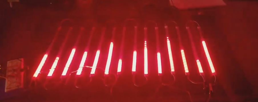
I finally received the rest of my LEDs where now I have a total of 280 LEDS (about 4.6 meters). I finally made some time to connect everything up and perform a strand test. See attached video. I'm running into a problem where once the strand test gets to over the 200-220th LED, power starts to die now. I measured it and it seems like I'm getting less than 3V. Too many LEDs are causing a voltage drop. I know for my spectrum analyzer, I'm not going to have them all at the same time but if I want this strand test to run nicely, would I need to purchase a another 5V 10amp power supply and wire it to the other end? Note that I provided another path from the power supply to the the 280th LED at the end.
Thanks in advance!
Eddie
Sorry. Couldn't upload so I put it on YouTube

280 LEDs @ 60mA = 16.8 A
You need to provide more than one extra wire into the 5V line. If you get another power supply then do not wire the positive so that it connects to the positive of the other supply.
But that's worst case scenario isn't it? The stand test probably draws that much current somewhere in the code i'm sure, but not all the time. I still need to create the rest of my code for the right hand channel of the spectrum analyzer to see if this power issue will even be an actual issue.
It is still a problem that I'm getting a reading under 3volts correct? or no...?
Also could you explain a little more about providing more than one extra wire into the 5V line? As I mentioned previously, I have another 5V line to the end of the LEDs...
It is still a problem that I'm getting a reading under 3volts correct? or no...?
Yes and is it 5V when you measure it at the power supply end when you see 3V where you do?
I have another 5V line to the end of the LEDs...
So have another one going into the center of the strip.
And maybe another two gong into the two spaces between the center tap and each end.
I'm just going to put the LEDs at 50% brightness since I don't have enough current for 100% brightness. I calculated out and at 50% brightness I only need 8.4 amps. I have a 10 amp power supply so that'll be good. I don't want to burn my eyes out haha.
On another note, I think I'd like to incorporate a push button to my project to switch colors. I'd like the button to work in the following way:
-Push Button: Make all LEDs Red
-Push Button: Make all LEDs Blue
-Push Button: Make all LEDs Green
-Push Button: Make LEDs rainbow
I'd like this to go into a loop. The user will just keep click until they stop on the color they want.
Can I do this with one button or do I need multiple buttons?
What would the code look like? Does anyone have any examples?
Thanks!
Yes with a single button. See FastLED/NeoPixel examples that are non-blocking? - LEDs and Multiplexing - Arduino Forum
You have to use a state machine style of programming, this thread shows you how.
Grumpy_Mike:
Yes with a single button. See FastLED/NeoPixel examples that are non-blocking? - LEDs and Multiplexing - Arduino ForumYou have to use a state machine style of programming, this thread shows you how.
Thanks Mike! You've been extremely helpful. I've learned so much since my first post. I am almost done with my project and finally going to hang it up in my living room to interface with my bluetooth system.
One last thing, I want to implement some code that will allow the top pixel of each Band to fall slowly like I've seen in other audio spectrum analyzers. Do you happen to know if any forums have this info?
Thanks Mike!
Eddie
I've attached my code in a txt file since I was exceeding the allowed character amount in my reply. In my code I currently have each LED as different color, but in the picture snip that I took during a video that I've attached along with the code shows the spectrum analyzer as red. I changed the LEDs to red just for the video.
I'm not sure where I would add my Falling LED code and my state machine code for implementing the button to change the colors of the LEDs. I'd appreciate any guidance.
Thanks,
Eddie
LED Audio Spectrum Analyzer - Horiztonal Colors.txt (14.4 KB)
Spoke too soon. I found the buttoncycler code in my neopixel examples. I think I'm on the right track here. I feel like my Cases will be fairly big since I need to call out each LED/Band and set them a certain color like I did in my void mapSpectrum code. I'm starting to understand here...man this code is getting large...
![]()
Okay, last post of tonight. I followed the following code from Adafruit:
// This is a demonstration on how to use an input device to trigger changes on your neo pixels.
// You should wire a momentary push button to connect from ground to a digital IO pin.  When you
// press the button it will change to a new pixel animation.  Note that you need to press the
// button once to start the first animation!

#include <Adafruit_NeoPixel.h>

#define BUTTON_PIN   2    // Digital IO pin connected to the button.  This will be
                          // driven with a pull-up resistor so the switch should
                          // pull the pin to ground momentarily.  On a high -> low
                          // transition the button press logic will execute.

#define PIXEL_PIN    6    // Digital IO pin connected to the NeoPixels.

#define PIXEL_COUNT 16

// Parameter 1 = number of pixels in strip,  neopixel stick has 8
// Parameter 2 = pin number (most are valid)
// Parameter 3 = pixel type flags, add together as needed:
//   NEO_RGB     Pixels are wired for RGB bitstream
//   NEO_GRB     Pixels are wired for GRB bitstream, correct for neopixel stick
//   NEO_KHZ400  400 KHz bitstream (e.g. FLORA pixels)
//   NEO_KHZ800  800 KHz bitstream (e.g. High Density LED strip), correct for neopixel stick
Adafruit_NeoPixel strip = Adafruit_NeoPixel(PIXEL_COUNT, PIXEL_PIN, NEO_GRB + NEO_KHZ800);

bool oldState = HIGH;
int showType = 0;

void setup() {
  pinMode(BUTTON_PIN, INPUT_PULLUP);
  strip.begin();
  strip.show(); // Initialize all pixels to 'off'
}

void loop() {
  // Get current button state.
  bool newState = digitalRead(BUTTON_PIN);

  // Check if state changed from high to low (button press).
  if (newState == LOW && oldState == HIGH) {
    // Short delay to debounce button.
    delay(20);
    // Check if button is still low after debounce.
    newState = digitalRead(BUTTON_PIN);
    if (newState == LOW) {
      showType++;
      if (showType > 9)
        showType=0;
      startShow(showType);
    }
  }

  // Set the last button state to the old state.
  oldState = newState;
}

void startShow(int i) {
  switch(i){
    case 0: colorWipe(strip.Color(0, 0, 0), 50);    // Black/off
            break;
    case 1: colorWipe(strip.Color(255, 0, 0), 50);  // Red
            break;
    case 2: colorWipe(strip.Color(0, 255, 0), 50);  // Green
            break;
    case 3: colorWipe(strip.Color(0, 0, 255), 50);  // Blue
            break;
    case 4: theaterChase(strip.Color(127, 127, 127), 50); // White
            break;
    case 5: theaterChase(strip.Color(127,   0,   0), 50); // Red
            break;
    case 6: theaterChase(strip.Color(  0,   0, 127), 50); // Blue
            break;
    case 7: rainbow(20);
            break;
    case 8: rainbowCycle(20);
            break;
    case 9: theaterChaseRainbow(50);
            break;
  }
}

// Fill the dots one after the other with a color
void colorWipe(uint32_t c, uint8_t wait) {
  for(uint16_t i=0; i<strip.numPixels(); i++) {
    strip.setPixelColor(i, c);
    strip.show();
    delay(wait);
  }
}

void rainbow(uint8_t wait) {
  uint16_t i, j;

  for(j=0; j<256; j++) {
    for(i=0; i<strip.numPixels(); i++) {
      strip.setPixelColor(i, Wheel((i+j) & 255));
    }
    strip.show();
    delay(wait);
  }
}

// Slightly different, this makes the rainbow equally distributed throughout
void rainbowCycle(uint8_t wait) {
  uint16_t i, j;

  for(j=0; j<256*5; j++) { // 5 cycles of all colors on wheel
    for(i=0; i< strip.numPixels(); i++) {
      strip.setPixelColor(i, Wheel(((i * 256 / strip.numPixels()) + j) & 255));
    }
    strip.show();
    delay(wait);
  }
}

//Theatre-style crawling lights.
void theaterChase(uint32_t c, uint8_t wait) {
  for (int j=0; j<10; j++) {  //do 10 cycles of chasing
    for (int q=0; q < 3; q++) {
      for (int i=0; i < strip.numPixels(); i=i+3) {
        strip.setPixelColor(i+q, c);    //turn every third pixel on
      }
      strip.show();

      delay(wait);

      for (int i=0; i < strip.numPixels(); i=i+3) {
        strip.setPixelColor(i+q, 0);        //turn every third pixel off
      }
    }
  }
}

//Theatre-style crawling lights with rainbow effect
void theaterChaseRainbow(uint8_t wait) {
  for (int j=0; j < 256; j++) {     // cycle all 256 colors in the wheel
    for (int q=0; q < 3; q++) {
      for (int i=0; i < strip.numPixels(); i=i+3) {
        strip.setPixelColor(i+q, Wheel( (i+j) % 255));    //turn every third pixel on
      }
      strip.show();

      delay(wait);

      for (int i=0; i < strip.numPixels(); i=i+3) {
        strip.setPixelColor(i+q, 0);        //turn every third pixel off
      }
    }
  }
}

// Input a value 0 to 255 to get a color value.
// The colours are a transition r - g - b - back to r.
uint32_t Wheel(byte WheelPos) {
  WheelPos = 255 - WheelPos;
  if(WheelPos < 85) {
    return strip.Color(255 - WheelPos * 3, 0, WheelPos * 3);
  }
  if(WheelPos < 170) {
    WheelPos -= 85;
    return strip.Color(0, WheelPos * 3, 255 - WheelPos * 3);
  }
  WheelPos -= 170;
  return strip.Color(WheelPos * 3, 255 - WheelPos * 3, 0);
}
I tested my button out with the code above before I started editing my code. My code is attached as a txt file. So I tried to follow the steps but the button is not working. I understand what the adafruit code is doing. It has 9 different code/conditions and it's calling them out. So everytime you press the button, that part of the code will be pulled and "uploaded". Now I did something similar, but I did not understand the delay(wait); part. Is that needed in mine? Is there any way I can shorten my code? It's getting pretty large. Any guidance would be appreciated.
Thanks,
Eddie
I apologize for so many posts tonight. Seems like I forgot to attach my code.See attached.
Led Audio Spectrum Analzyer Code with ButtonCycler.txt (47.7 KB)
So I tried to follow the steps but the button is not working.
I think it is but your code only gets to look at the button at the end of a cycle. That is why I wrote that code I linked to, it is a state machine that doesn't hog the processing during the delay but uses that time to look at the button, so making it "work".
The MSGEQ7 chip will drop the peak value slowly, the speed of drop depends on how often you read the chip. So to drop it slower only read it "so often" as defined by a millis time rather than read it as fast as the loop will let you.
Any code that repeats close to the same thing over and over can be replaced by a loop.
Look at this bit:-
if (Pixel == 0)
                                {
                                                Strip.setPixelColor(SpectrumGraphLeft[Band][0], 91, 2,47);
                                }
Notice that the second index of SpectrumGraphLeft is the pixel number, and the 91, 2, 47 numbers all change with the value of the Pixel variable. So make an array of these numbers, call then say red[] , green[], blue[] and fill them with the values you want, so then the whole of that section of code becomes:-
for(int Pixel = 0; Pixel < 20; Pixel++){
    Strip.setPixelColor(SpectrumGraphLeft[Band][Pixel], red[Pixel],green[Pixel],blue[Pixel]);
}
see how much shorter this is than your code?
Amazing...that makes total sense! I will try to play with my code when I get off work. I'll put something together and keep you updated. Thanks Mike! I really appreciate the help.
On another note, I was trying to find some "Falling Led" code in the forums, but no luck...The only thing I found was something for FFT? Not sure if I could do somthing similar.
    #include <avr/pgmspace.h>
    #include <ffft.h>
    #include <math.h>
    #include <Adafruit_GFX.h>   // Core graphics library
    #include <RGBmatrixPanel.h> // Hardware-specific library

    #define CLK  8  // MUST be on PORTB!
    #define LAT  9
    #define OE   9
    #define A   A0
    #define B   A1
    #define C   A2
    RGBmatrixPanel matrix(A, B, C, CLK, LAT, OE, false);

    #define       ADC_CHANNEL 3      // Analog pin
    int16_t       capture[FFT_N];    // Audio capture buffer
    complex_t     bfly_buff[FFT_N];  // FFT "butterfly" buffer
    uint16_t      spectrum[FFT_N/2]; // Spectrum output buffer
    volatile byte samplePos = 0;     // Buffer position counter
    // In library file ffft.h, FFT_N *must* be set to 64.  Due to the RGB
    // matrix overhead, there's only enough RAM for a 64 sample FFT buffer
    // (32 spectrum outputs).  Any higher WILL fail!

    byte
      peak[32],        // Peak level of each column; used for falling dots
      count = 0;       // Frame counter for delaying dot-falling speed
    int
      minLvlAvg = 0,   // For dynamic adjustment of low & high ends of the graph,
      maxLvlAvg = 512; // pseudo rolling averages for the prior few frames.
    // These two tables help the graph adjust dynamically to varying input:
    PROGMEM uint8_t
      // This is low-level noise that's subtracted from each FFT output column:
      lower[32] = { 44,28,5,6,4,3,3,5,3,4,5,4,4,4,4,5,
                     3,4,4,3,4,4,4,4,4,3,4,3,4,3,4,5 },
      // These are scaling quotients for each column.  Partly for filtering out
      // low-frequency (~150 Hz) noise from the FFT, and also because most music
      // is simply heavy toward the low end (rhythm, bass).
      upper[32] = { 200,160,90,48,23,11,5,3,1,1,0,0,0,0,0,0,
                      0,  0, 0, 0, 0, 0,0,0,0,0,0,0,0,0,0,0 };

    void setup() {
      memset(peak, 0, sizeof(peak));
      matrix.begin();

      // Init ADC free-run mode; f = ( 16MHz/prescaler ) / 13 cycles/conversion
      ADMUX  = ADC_CHANNEL; // Channel sel, right-adj, use AREF pin
      ADCSRA = _BV(ADEN)  | // ADC enable
               _BV(ADSC)  | // ADC start
               _BV(ADATE) | // Auto trigger
               _BV(ADIE)  | // Interrupt enable
               _BV(ADPS2) | _BV(ADPS1) | _BV(ADPS0); // 128:1 / 13 = 9615 Hz
      ADCSRB = 0;                // Free run mode, no high MUX bit
      DIDR0  = 1 << ADC_CHANNEL; // Turn off digital input for ADC pin
      TIMSK0 = 0;                // Timer0 off

      sei(); // Enable interrupts
    }

    void loop() {
      char     c;
      byte     x, y, y2, r, g, b;
      int      hue, minLvl, maxLvl;
      uint16_t n;
      long     level;

      while(ADCSRA & _BV(ADIE)); // Wait for audio sampling to finish

      fft_input(capture, bfly_buff);   // Samples -> complex #s
      samplePos = 0;                   // Reset sample counter
      ADCSRA |= _BV(ADIE);             // Resume sampling interrupt
      fft_execute(bfly_buff);          // Process complex data
      fft_output(bfly_buff, spectrum); // Complex -> spectrum

      // Get min & max levels in FFT output:
      for(x=0; x<32; x++) {
        level = (long)spectrum[x] - (long)pgm_read_byte(&lower[x]); // rm noise
        if(level < 0L) level = 0L; // Clip...else fixed-point scale:
        else           level = (level * (256L - pgm_read_byte(&upper[x]))) >> 8;

        if(x == 0) {
          minLvl = maxLvl = level;
        } else {
          if(level < minLvl)      minLvl = level;
          else if(level > maxLvl) maxLvl = level;
        }
      }
      // minLvl and maxLvl indicate the extents of the FFT output, used
      // for vertically scaling the output graph (so it looks interesting
      // regardless of volume level).  If they're too close together though
      // (e.g. at very low volume levels) the graph becomes super coarse
      // and 'jumpy'...so keep some minimum distance between them (this
      // also lets the graph go to zero when no sound is playing):
      if((maxLvl - minLvl) < 8) maxLvl = minLvl + 8;

      minLvlAvg = (minLvlAvg * 7 + minLvl) >> 3; // Dampen min/max levels
      maxLvlAvg = (maxLvlAvg * 7 + maxLvl) >> 3; // (fake rolling average)

      // Render display:
      for(x=0, hue=0; x<32; x++, hue += 40) { // For each column...
        level = (long)spectrum[x] - (long)pgm_read_byte(&lower[x]); // rm noise
        if(level < 0L) level = 0L; // Clip...else fixed-point scale:
        else           level = (level * (256L - pgm_read_byte(&upper[x]))) >> 8;
        // Second fixed-point scale based on dynamic min/max levels:
        level = ((level - minLvlAvg) * 16L) / (long)(maxLvlAvg - minLvlAvg);

        // Clip output and convert to byte (column height...0 to 16):
        if(level < 0L)       c = 0;
        else if(level > 16L) c = 16;
        else                 c = (char)level;

        if(c > peak[x]) peak[x] = c; // Keep white dot on top

        if(peak[x] <= 0) { // Empty column?
          matrix.drawLine(x, 0, x, 15, 0);
          continue;
        }

        y = 16 - peak[x]; // y = 0 to 15
        if(y > 0) matrix.drawLine(x, 0, x, y-1, 0); // Fill black above peak
        // WILL CRASH HERE if out of RAM!
        matrix.drawPixel(x, y, 0xffff); // Draw white dot at peak

        // Draw fading streak from below peak to just above current level
        for(y++, y2 = 16 - c, n=150; y < y2; y++) {
          matrix.drawPixel(x, y, matrix.ColorHSV(hue, 255, n, true));
          if(n >= 50) n -= 50;
        }

        // Draw bar for current level, with slight glow at top
        y = y2;
        n = 100;
        // If current level is peak, don't overwrite white dot
        if(c == peak[x]) {
          y++;
          n = 150;
        }
        while(y < 16) {
          matrix.drawPixel(x, y, matrix.ColorHSV(hue, n, 255, true));
          n += 50;
          if(n > 255) n = 255;
          y++;
        }
      }

      // Every alternate frame, make the peak pixels drop by 1:
      if(++count == 1) {
        count = 0;
        for(x=0; x<32; x++) {
          if(peak[x] > 0) peak[x]--;
        }
      }
    }

    ISR(ADC_vect) { // Audio-sampling interrupt
      static const int16_t noiseThreshold = 4;
      int16_t              sample         = ADC; // 0-1023

      capture[samplePos] =
        ((sample > (512-noiseThreshold)) &&
         (sample < (512+noiseThreshold))) ? 0 :
        sample - 512; // Sign-convert for FFT; -512 to +511

      if(++samplePos >= FFT_N) ADCSRA &= ~_BV(ADIE); // Buffer full, interrupt off
    }
Mike, should by mapspectrum look like this for the button cycler?
void mapSpectrum()    // map spectrum to pixel strips
{
  for(byte Band=0 ; Band <7 ; Band++)
  {
    SpectrumLeft[Band] = map(SpectrumLeft[Band],100 , 800, 0, 19);
    SpectrumRight[Band] = map(SpectrumRight[Band], 45, 800, 0, 19);

                for(int Pixel = 0; Pixel < 20; Pixel++){
                                Strip.setPixelColor(SpectrumGraphLeft[Band][Pixel], red[Pixel],green[Pixel],blue[Pixel]);
}

                for (byte Pixel = SpectrumLeft[Band] ; Pixel < 20 ; Pixel++)
                                {      // Turn the rest OFF!
                                                Strip.setPixelColor(SpectrumGraphLeft[Band][Pixel], OffColor);
                                }    // end for (Pixel

                 for(int Pixel = 0; Pixel < 20; Pixel++){
                                Strip.setPixelColor(SpectrumGraphRight[Band][Pixel], red[Pixel],green[Pixel],blue[Pixel]);
}

                for (byte Pixel = SpectrumRight[Band] ; Pixel < 20 ; Pixel++)
                                {      // Turn the rest OFF!
                                                Strip.setPixelColor(SpectrumGraphLeft[Band][Pixel], OffColor);
                                }    // end for (Pixel


  }    // end for (Band
  Strip.show();


}
Im not understanding the cases. ![]() Sorry, Im getting confused...
Sorry, Im getting confused...