Hello Arduino Community,
I am currently working on a Home Warning System project using various components, and I would appreciate any recommendations or feedback on the wiring diagram. This is a new project that me and my teammates will try to make after my other project beforehand.
Purpose: The Home Warning System is designed to enhance home safety by detecting fire, gas leaks, and motion. It will send alerts through a GSM module and sound an alarm using a Piezo buzzer. The components used in this project include an Arduino Uno, DHT22 sensor, MQ-2 gas sensor, ESP32-CAM, SIM900A GSM module, and a Piezo buzzer. The system aims to provide real-time alerts to homeowners in case of any hazards.
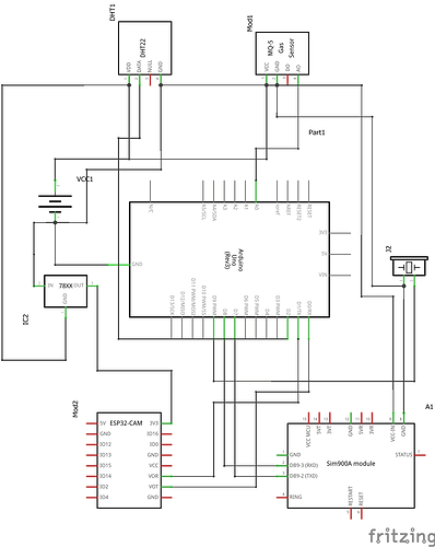
Wiring Diagram: Here is a brief overview of the connections:
- DHT22 Sensor:
- VCC to 5V on Arduino
- GND to GND on Arduino
- DATA to digital pin 2 on Arduino
- MQ-2 Gas Sensor:
- VCC to 5V on Arduino
- GND to GND on Arduino
- AO to analog pin A0 on Arduino
- ESP32-CAM:
- 3V3 to the output of the 7805 voltage regulator (3.3V)
- GND to GND on Arduino
- TX to RX (Pin 0) on Arduino
- RX to TX (Pin 1) on Arduino
- SIM900A GSM Module:
- VCC-IN to 5V on Arduino
- GND to GND on Arduino
- TXD to SoftwareSerial RX (pin 7) on Arduino
- RXD to SoftwareSerial TX (pin 8) on Arduino
- Piezo Buzzer:
- Positive terminal to digital pin 9 on Arduino
- Negative terminal to GND on Arduino
- Power Supply:
- Battery pack connected to the 7805 voltage regulator
- 7805 OUT to 3.3V rail
- 7805 GND to GND rail
I have attached the schematic for reference. Could you please review the wiring diagram and provide any recommendations or improvements to ensure the system operates correctly?
Thank you in advance for your assistance!

