See, that wasn't how i was looking at it. I was looking at it with 10-pole rotary switches, where you have a common, and each position/pole represented a different numerical digit. I understand binary/octal/hexadecimal, but I don't understand how the switch gets octal out of a position. In which case, an arduino wouldn't be needed, the switches would feed directly to the shift register (which i dont understand either)
You can find mechanical switches like that. You didn't say what you had, that's why I asked.
Your method will require 10 input pins. The alternate just 4. How many IO pins do you have available?
An ATMega168 or ATMega328 part can do this task with its 20 IO pins; or you can have unique IO pins for all the switches and all the segment drivers and use a much larger microcontroller that costs more, but only need a buffer for each LED segment.
CrossRoads:
You can find mechanical switches like that. You didn't say what you had, that's why I asked.
Your method will require 10 input pins. The alternate just 4. How many IO pins do you have available?
An ATMega168 or ATMega328 part can do this task with its 20 IO pins; or you can have unique IO pins for all the switches and all the segment drivers and use a much larger microcontroller that costs more, but only need a buffer for each LED segment.
Tradeoffs, tradeoffs ...
I posted a link some pages up to the 10 position switched, after the simple drawing.
I would like to use the cheaper arduino uno, but it doesn't have enough outputs for the 3 displays (21 pins total, plus the input). So I'm thinking I'm stuck with the mega 2560.
but if I can reduce wires and complications using the octal switches, I'm all for it!
Do you have a schem for it? How hard is it to program, and I'm guessing you have it set to increment on button press? How would I modify that for the multiple inputs per display, or would each display have it's own board like that?
since power is cut after each pass, the other nice thing about 10 pile rotary switches, is that they're solid state, and will hold after power loss. Unless I could somehow write the last number to memory and have it come up when power is re-initiated, and be controlled using up/down buttons.
The other switches are just read on a periodic basis (10 mS?), display is updated as soon as they are read.
Being mechanical also, they will display the same until changed.
The other switches are just read on a periodic basis (10 mS?), display is updated as soon as they are read.
Being mechanical also, they will display the same until changed.
This will be simple to program.
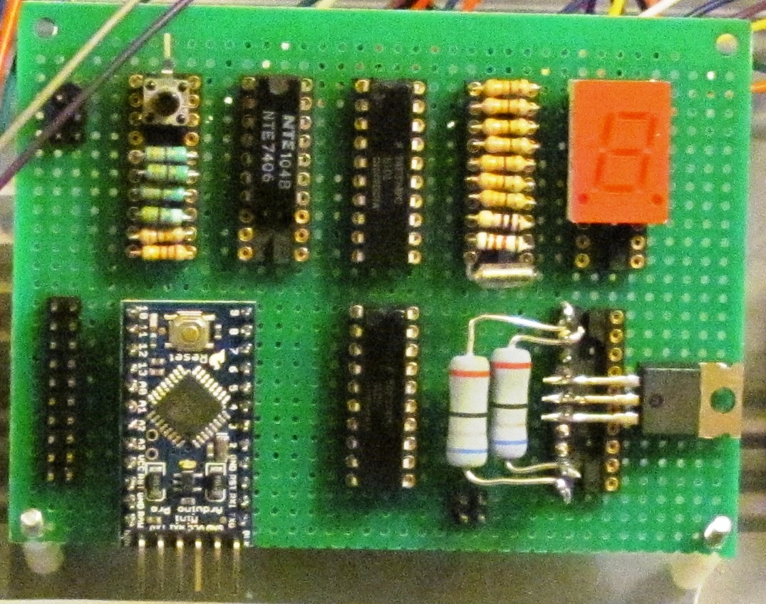
that makes things very much more clear! Thank You. Looks very simple indeed, just a few IC's and resistors for each segment. Very nice. And thank you for taking the time to draw it
So the pro-mini reads the switches, sends the chips a serial form of the number, and the chips decode it per display?
"So the pro-mini reads the switches," Yes
"sends the chips a serial form of the number, " Yes
" and the chips decode it per display?" No, that decoding is done in the software.
For example, to have the digit 1 display, you would allow segments B & C to turn on
A
F B
G
E C
D
and turn off the rest.
So with DRN0 controlling SegmentA
1 -> B
2 -> C
3 -> D
etc.
and if DRN0 is bit 0 in a databyte, you would send out 1 to turn Off a segment and 0 to leave on a segment
Thus data byte B11111001
would turn off all but Segments B & C , thus displaying a 1 on the display.
That makes sense. So we're setting each display panel to be a binary bitstring, where each position is a segment.
So arduino is taking the switch value, converting it to a bitstring, send it in serial form to the 595's, and they check the position-value for each digit, turn on 0's and turn off 1's.
seems straight forward.
How do I tell each 595 what set of serial data to listen to?
In your void loop code, after reading the switches and deciding what you want to send, you will have
digitalWrite(D2, LOW); // sets up the parts to receive data
// format: shiftOut(dataPin, clockPin, MSBFIRST, databyte);
shiftOut(D4, D3, MSBFIRST, byte1); // may need to swap byte1 & 3,
shiftOut(D4, D3, MSBFIRST, byte2); // or possibly use LSBFIRST,
shiftOut(D4, D3, MSBFIRST, byte3); // have to see how your output & order looks
digitalWrite(D2, HIGH); // moves the data to the shift register output pins
so D2 tells the 595's that the data is coming, synchronizes the clocks on D3, and sends the byte on D4?
Sort of - D2 goes low, opens the shift register for receiving data.
Data is output on D4, D3 clocks it into the shift register - the software makes that happen 8 times for a byte.
(the software looks like: output bit x of D4, output D3 Hi then Lo, repeat for 7 more bits)
Three bytes are sent out, shifting thru the data thru registers.
When the shifting is done, D2 going high puts the data on the output pins of all three parts at once so they appear to be updated at the same time.