I'm thinking use a transistor to convert the Arduino's 5V output to a 10V @ 25mA output going to each display segment. Vs will be 12 volts, so 400 ohm resistor on the Vs line I figure?
I thinking connect digital pin to base, Vs power line to collector, and the LED segment to emitter.
They make a CA but only in a 5 inch, and I think that would be too big for what I'm doing.
What makes a CC harder to drive than a CA? If it was a CA, could I just write the analog pins to be zero volts, or would the 10V Vs just zap the sockets? (The arduino running on a 5V regulator off same 12V power brick)
So for the driver you specified, pin 9 would be my 10V, the inputs on left woult be the arduino 5V signal, and the outputs would be the 10V going to each segment?
Mouser doesn't seem to have that part number, not sure what to C/R to.
(I prefer ordering from mouser because they're 3 miles away, no shipping, no wait time)
Because with a common anode all you have to do is to pull down to ground with a transistor or transistor array, these are quite common and cheap as you have found.
With common cathode you have to have a source of voltage generated from the arduino. As this is a much rarer situation and needs more electronics to achieve these are more expensive.
Many beginners are in the mindset that common cathode is the sensible straightforward thing to have, in this they are mistaken.
CrossRoads circuit technique is called shunt switching, and consumes more power when the LEDs are off than when they are on.
The ULN2003 is 67 cents at mouser for 7 array, the ULN2803 is $1 at mouser for 8 array.
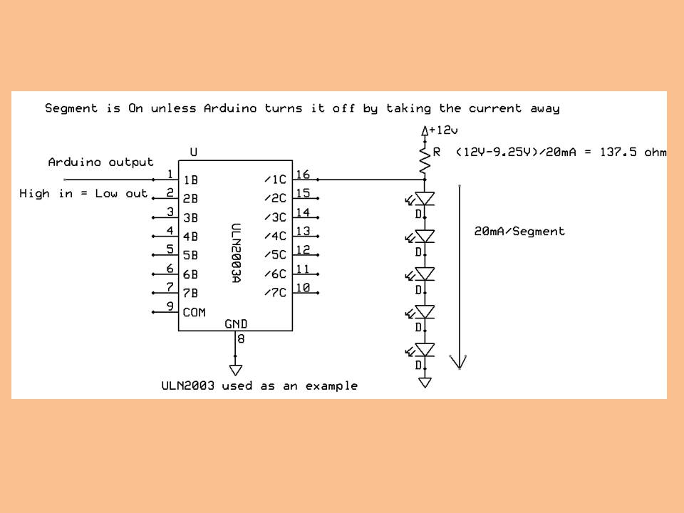
It takes more current because having the arduino output turned on is what turns off the LED segmant?
How many mA are we talking about? This is going on a 12V/1A power brick with voltage regulators so I think I would be fine.
So if I understand that, the darlington array "steals" the ground and re-routes it around the LED segment, so it does not light? Arduino 5V signal goes to base, LED Vs goes to collector, and emitter goes to ground.
It takes more current because having the arduino output turned on is what turns off the LED segmant?
Yes.
the darlington array "steals" the ground and re-routes it around the LED segment, so it does not light?
Yes the darlington shorts out the LEDs.
How many mA are we talking about?
When the LEDs are on there is 20mA going through them. But when the LEDs are off there is:-
12 / 137.5 = 87.2 mA going through the darlington, and it is burning 12 X 0.0872 = 1.05 Watts, so it needs to be a big resistor.
Check newark, digikey, dipmicro.com for prices as well.
Takes more current in the sense that current is always on, vs only being on when the LED is on.
20-25ma/segment if you are running full brightness. So 175mA per digit to display an 8, 200 with decimal point.
Yes.
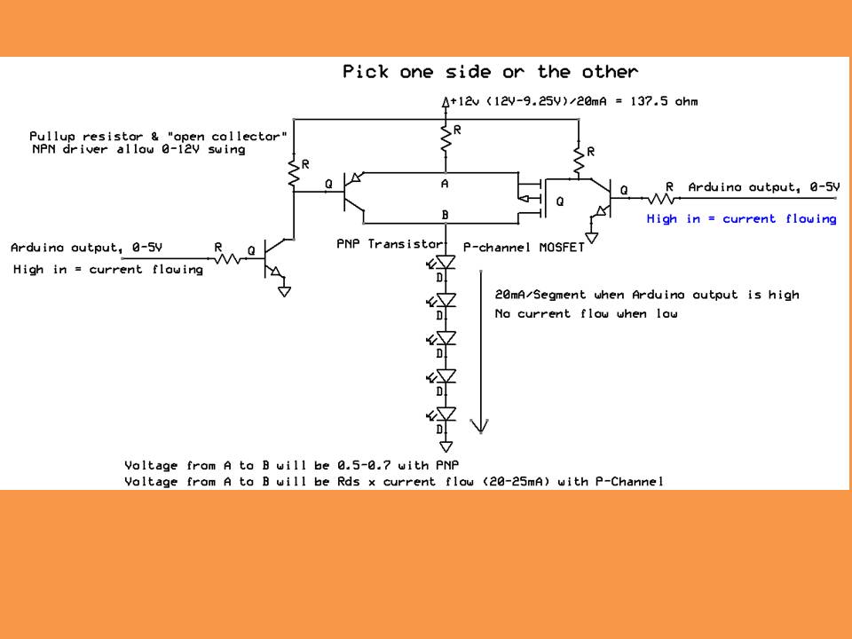
The other option is to put a PNP transistor, or P-Channel MOSFET, between +12V and the individual segment Anodes,
i.e. "roll your own" driver.
The Allegro 2981 part does that in an array of 8 drivers; unfortunately it has a 1.8V drop from +12V to the output.
It takes more current because having the arduino output turned on is what turns off the LED segmant?
Yes.
the darlington array "steals" the ground and re-routes it around the LED segment, so it does not light?
Yes the darlington shorts out the LEDs.
How many mA are we talking about?
When the LEDs are on there is 20mA going through them. But when the LEDs are off there is:-
12 / 137.5 = 87.2 mA going through the darlington, and it is burning 12 X 0.0872 = 1.05 Watts, so it needs to be a big resistor.
Yes they can take 500mA each with a total per package not exceeding about 650mA.
So if I were display a "1", 5 segments would be turned off @ ~95mA (add some overhead) = 475 mA
So between the Arduino, voltage regulators, darlington chips, and LED boards (remember I'm driving 2 boards), if I displayed a 1 on both boards, I'd be pulling about 1 3/8 amps. So I guess a 12VDC @ 2 amp power brick it is.
CrossRoads:
Okay, that much IO you're gonna need some shift registers.
These are available at mouser http://www.ti.com/lit/ds/symlink/tpic6595.pdf
Output shift register with high voltage/high current sink output driver
If you have a part number for the rotary switches, can suggest parts for that too.
A shift register is a device you can store an 8-bit value in.
The darlington array is just a buffer that can drive more current.
The tcip6595 combines both into 1 part.
If you look at the data sheet for the rotary switch, the pinouts and truth table, you will see the 1-2-4-8 output pins, the switch makes contacts internally to output a binary code of the digit selected: 0000, 0001, 0010, 0011,0100, 0101, 0110, 0111,1000,1001 for 0-9.
What this used for? Showing 5:xx and 8:xx as prices? Just curious.
it wont look as pretty, but if I can make it for much cheaper, why not?
Our drag car is 5.55 in the 1/8 mile and 8.67 in the 1/4, so that's how the first digit is chosen. But the 2 decimal places can be anything based on the conditions.