Transistor to control a DC Motor

Two of my students are trying to use a 2N2222 transistor to toggle a simple DC Motor on and off. When I connect a LED to the output that goes to the transistor base pin it lights, so I know it's sending signal. And when I connect the motor directly to the power it runs. But when I introduce the transistor it doesn't toggle the motor.

Logic Flow:
Button or limit switch pressed ---> Light an LED and turn on the motor
Neither the button or limit switch passed ---> Turn off the light and motor.

Light works, but motor dos not. Wiring and Code follows. Resistors are representative of the correct values in the circuit. The transistor is a 2N2222. I used TinkerCAD to illustrate the wiring, so it shows a 3-way switch, but in reality it's a limit switch commonly used on a 3D printer.

int LimitInputPin = 7;
int LEDOutputPin = 2;
int ButtonInputPin = 4;
int MotorOutputPin = 13;

void setup() {
  pinMode(LimitInputPin, INPUT);
  pinMode(LEDOutputPin, OUTPUT);
  pinMode(ButtonInputPin, INPUT);
  pinMode(MotorOutputPin, OUTPUT);
}

void loop() {
  if ((digitalRead(LimitInputPin)==HIGH)||(digitalRead(ButtonInputPin)==HIGH)){
    digitalWrite(LEDOutputPin,HIGH);
    digitalWrite(MotorOutputPin,HIGH);

  }
  if ((digitalRead(LimitInputPin)==LOW)&&(digitalRead(ButtonInputPin)==LOW)){
    digitalWrite(LEDOutputPin,LOW);
    digitalWrite(MotorOutputPin, LOW);
  }
  if ((digitalRead(LimitInputPin)==HIGH)&&(digitalRead(ButtonInputPin)==HIGH)){
    digitalWrite(MotorOutputPin,HIGH);
  }
}
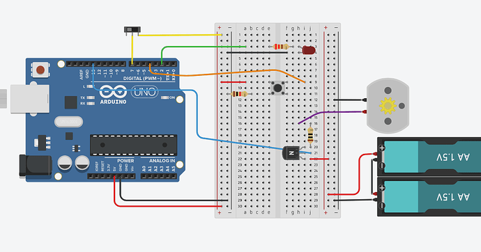
Follow this tutorial on how to hook-up the motor and 2N2222

Also connect the grounds together

Making adjustments.

Maybe it is a good idea to connect a 10k resistor from the input to GND in order to drain the input when the switch is open. An open input can cause undefined states on the Arduino and this will cause strange effects on the program. Maybe in your case here this is not the problem but I just wanted to mention because I had problems with this and after using the pulldown resistor I never had this problem again.

A transistor should have a base resistor. 180 ohm will be around good.

  1. Switch on pin 7 connected incorrectly. Arduino pin will float and not reliably read HIGH or LOW.
  2. Button on pin 4 may not be correctly connected, pull-down resistor not necessary if button connected between pin and ground and INPUT_PULLUP used.
  3. No resistor to limit current between Arduino pin 13 and transistor base, could damage Arduino.
  4. Current limiting resistor in series with motor probably preventing motor from running.
  5. No flyback diode in parallel with motor. Could damage transistor and Arduino.
  6. No suppression capacitor in parallel with motor could cause interference with Arduino.
  7. No common ground between Arduino and battery.
  8. Motor current may be too high for breadboard use.
1 Like
  1. I'm not sure why the switch on pin 7 would correctly trigger the LED but not the motor if it was not reliably reading.

  2. The button correctly signals the Arduino to activate the light when pressed, the same conditional statement should set pin 13 to high to activate the transistor and thus the motor. And to this end I connected pin 13 to another LED instead to see what it was doing and that lights. So it's setting pin 13 to high, but the transistor setup seems to be the problem.

  3. Added a resistor there. No change.

  4. Rewired without resistor in series with motor. No change.

  5. Diode added. No change.

  6. Added 100nF capacitor in parallel with motor. No change.

  7. Common ground added. No change.

  8. Motor works when plugged directly into the power from the battery via the breadboard.

it doesn´t look quite clear how your transistor circuit is built, anyway it should look like this one...


the diode and the capacitor are just to eliminate bad inductive response from the motor coils.
connect one side of the motor directly to your external battery + , not to the 5V output of the processor.

Always show us a good schematic of your proposed circuit.
Show us a good image of your ‘actual’ wiring.
Give links to components.

Also, when you make alterations, we need to see the above information again.

Did the transistor die due to lack of everything (base resistor, diode, caps).
Maybe try a new one...

Luck. In one switch position, pin 7 is connected to Vcc and will reliably read HIGH. In the other switch position, pin 7 is connected neither to Vcc or ground, it is floating and won't give a reliable reading.

Ok, I only said may be incorrectly wired. It's hard to remember/tell with those 4-pin buttons. You seem to have chosen the right pins. To avoid any problems, use only a diagonally opposite pair of pins and leave the other 2 pins unconnected. If you wire the button like that, and between the Arduino pin and ground, you can save using 1 resistor by using the Arduino's internal pull-up resistor instead. This also removes the risk of the +V connection to the switch coming loose in the final circuit and causing a damaging short-circuit.

No change you have noticed, but you have removed the potential for further damage to the Arduino pin. The pin may already be partially damaged by the excessive current that would have flowed from out of the pin to the transistor base.

Because something else is the problem. But, all other things being correct, that resistor could have slowed or stopped the motor running, and could have overheated itself.

Again, no change you noticed because the motor is not running. But once it is running, when it stops, a spike of negative current would flow as the motor comes to a stop. That negative current could damage the transistor or the Arduino, and may have already done so. The flyback diode protects against that by allowing that negative current to dissipate through it.

The brushes in motors can cause interference with nearby circuits, causing the Arduino to behave strangely, for example. This cap helps to suppress any interference.

Without that, the transistor would not switch on, because current cannot flow from the Arduino pin, through the resistor and into the transistor base pin, out of it's emitter pin and back to the Arduino ground.

Fine. We know nothing about the specs of the motor you are using. I guess it's current is not very high. But Breadboard contacts are not rated for high currents, 1A would be a sensible limit to stick to. Don't forget that when a motor is stalled, the current it draws could be at least 5x what it draws when running freely.

Which one? The collector and emitter leads are reversed.
2N22222N2222
or
P2N2222
P2N2222

If you connected everything as in the Adafruit turtorial and it does not work, then you probably burned out he transistor, try another.

This topic was automatically closed 180 days after the last reply. New replies are no longer allowed.