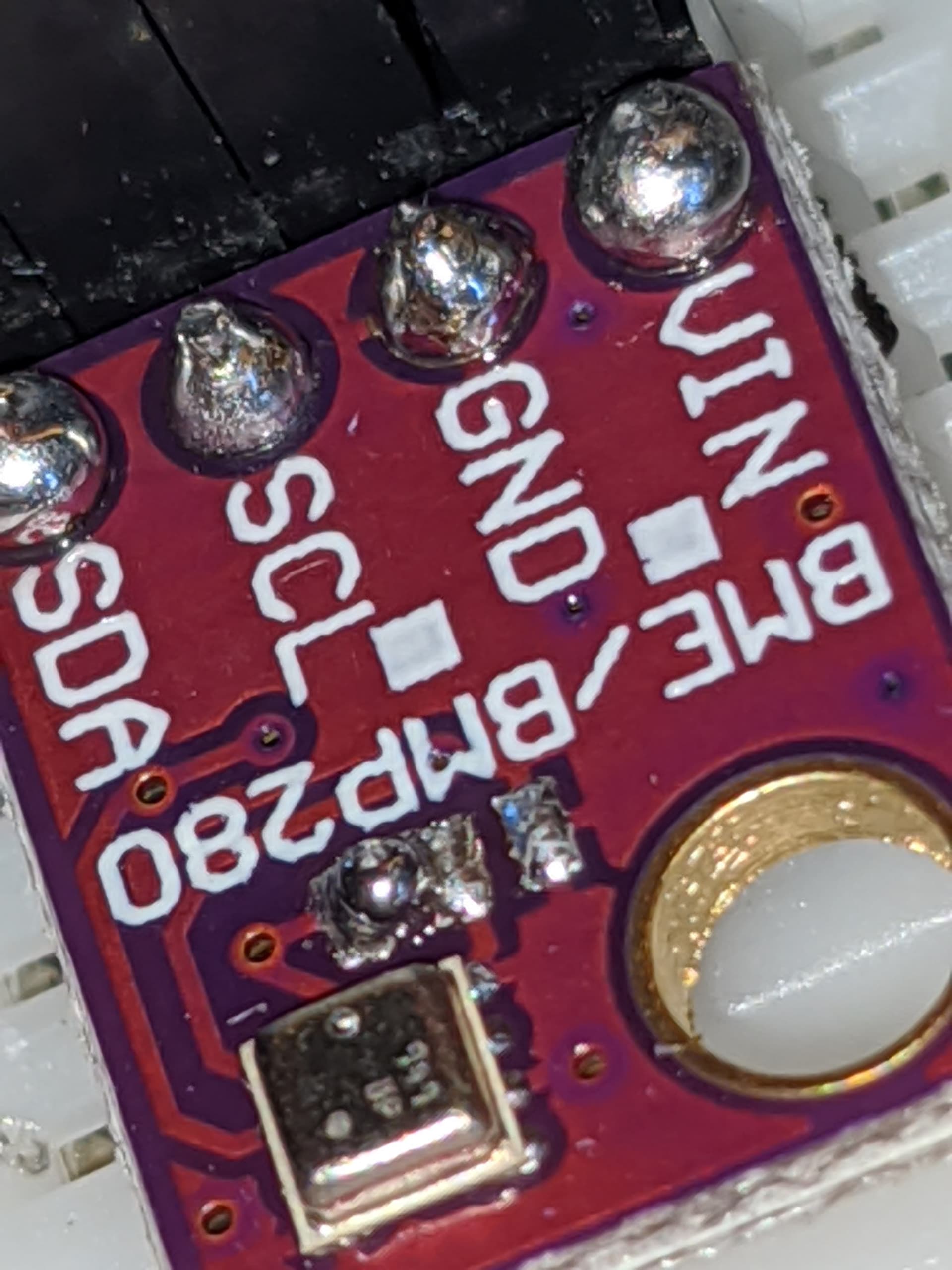
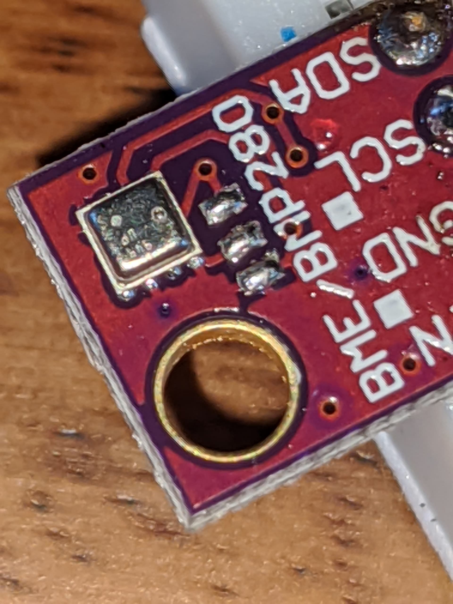
I understand that in order to change the address of the BME280, you have to scratch the trace off between 2 of the ground pads, and then join 2 of the ground pads.
The odd thing is that my BME280 chips didn't seem to have a trace between the two ground pads on the right. So, I just didn't do anything to them, and jumped the two pads on the left.
The outcome here is that it isn't being recognized by my NodeMCU.
I have another BME280 chip which I haven't modified in anyway, and it is being recognized by the nodeMCU on the 0x76 channel, which is the default.
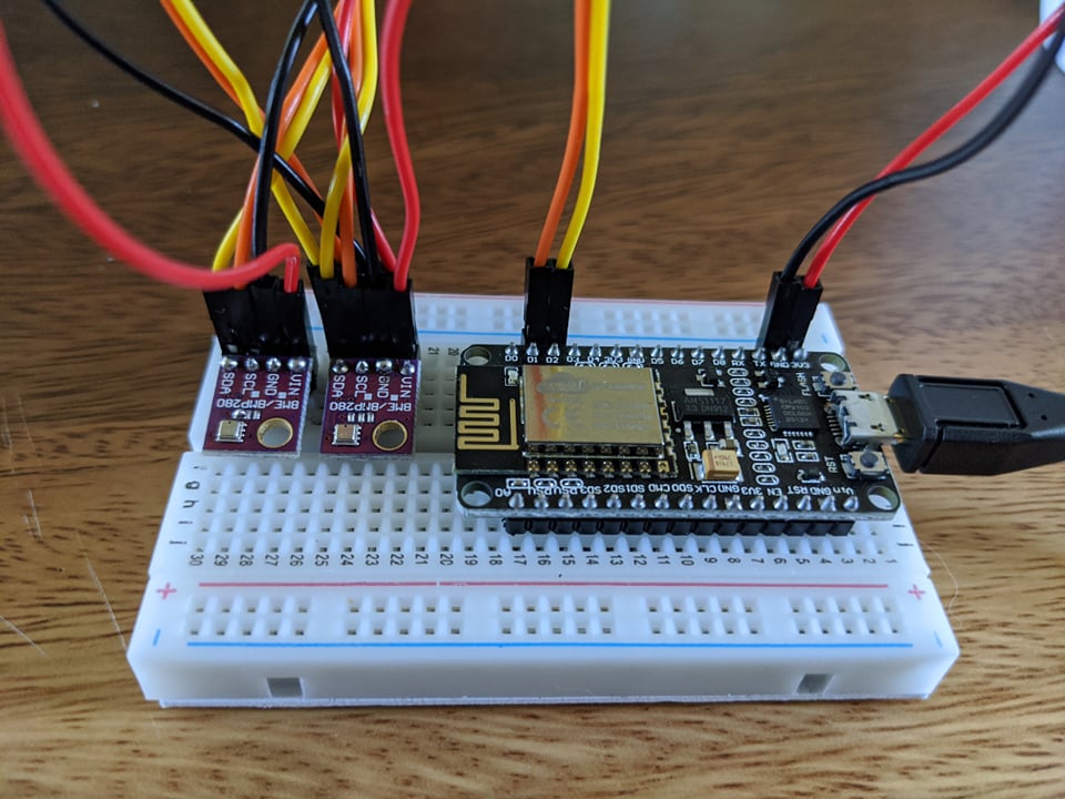
When I set them up in series like below, only the unmodified BME280 is recognized. The unmodified chip independently wired to the board gets recognized. The modified chip wired independently to the board doesn't get recognized.
I haven't had much luck using jumper wires with I2C. Sometimes it works, sometimes it doesn't. I usually end up just making a harness and hardwiring it.
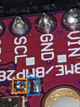
There are three rectangular pads on this board. Remove the solder from the left pair and make a solder jumper on the right pair.
Remove orange,
Add blue
When your are done, you should run this program. It scans the I2C bus and lists every device on the bus.
#include <Wire.h>

void setup() {
  Wire.begin();

  Serial.begin(9600);
  while (!Serial);             // Leonardo: wait for serial monitor
  Serial.println("\nI2C Scanner");
}

void loop() {
  byte error, address;
  int nDevices;

  Serial.println("Scanning...");

  nDevices = 0;
  for (address = 1; address < 127; address++ )
  {
    // The i2c_scanner uses the return value of
    // the Write.endTransmisstion to see if
    // a device did acknowledge to the address.
    Wire.beginTransmission(address);
    error = Wire.endTransmission();

    if (error == 0)
    {
      Serial.print("I2C device found at address 0x");
      if (address < 16)
        Serial.print("0");
      Serial.print(address, HEX);
      Serial.println("  !");

      nDevices++;
    }
    else if (error == 4)
    {
      Serial.print("Unknown error at address 0x");
      if (address < 16)
        Serial.print("0");
      Serial.println(address, HEX);
    }
  }
  if (nDevices == 0)
    Serial.println("No I2C devices found\n");
  else
    Serial.println("done\n");

  delay(5000);           // wait 5 seconds for next scan
}
So you're telling me I jumped the wrong grounds!? AGH!
What would be the expected result of jumping the wrong grounds? Would it still be recognized? Because it's not being recognized.
I'm actually using a preloaded firmware from homeassistant. I'm unsure what the I2C debugging code is like on it, but it returns the same phrases you've listed. I can try to figure that out later.
I'll have to order a solder sucker and get back to you.
The chip you uploaded looks like the standard BME280--the pad on the left has a trace line over to the pad in the middle. On mine, that trace line doesn't exist. That's what you're supposed to scratch off, and then you're supposed to fuse the right bumper and the middle bumper.
MAYBE the only trace line coming from my middle bumper is that trace line?
If your question is solved, please tick the solution checkbox under the most useful reply; that way others that have the same question know that a solution ws provided.
Look at the following diagrams to see what is going on in the BME280 chip itself and the breakout board with respect to I2C address.
1. 5V Vcc supply and 5V logic breakout board for 3.3V BME280 sensor.
Figure-1:
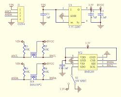
2. The following (Fig-2) is the schematic of Fig-1 of Step-1.
Figure-2:
Figure-2 clearly shows that the I2C address for breakout borad of Fig-1 is 0x76 (the AD0-pin is grounded).
3. If you want to use two BME280 sensors, I would suggest to use the following 3.3V Supply voltage and 3.3V Logic Breaout Board (Fig-3) which is compatible with NodeMCU without any additional level sifters and voltage regulator. It supports both I2C and SPI protocols.
Figure-3:
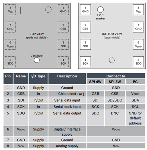
4. Breakout Board of Fig-3 can be connected with NodeMCU in I2C Mode using the information of the following Table (Fig-4) and wiring of Step-5.
I would greatly prefer to just use the hardware I already have. My system is compatible with it, I just can't figure out how to change the I2C address on my second sensor.
Figure-2 is very low resolution, and really I'm quite the noob. So, even if it weren't, I'd have a hard time using it to determine what additional modifications I'd need to make in order to change the address to 0x77.
The 5V supply/5V logic BME280 breakout boardd that you are using has the I2C address permanently fixed to 0x76 by grounding the AD0-pin of the sensor. This is what has been shown in Fig-2 of Post-10.
The breakout borad is a double layer (or multi layer?) PCB with SMD devices. I am worried about how you are going to cut the PCB track of one breakout board, detect the AD0-pin of the sensor and tie it with 3.3V to assign the I2C address at 0x77.
The viable option could be the use of breakout board of Fig-3 of Post-10; where, the AD0-pin is exposed as SD0 signal and could be tied to GND or 3.3V to assign I2C address at 0x76 or 0x77 respectively.
Shall we say that it is not possible with this module ?
According to the datasheet: "The SDO pin cannot be left floating; if left floating, the I2C address will be undefined".
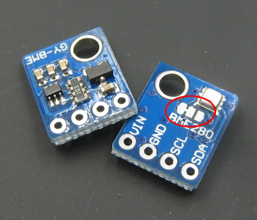
The middle one needs to be free from the ground area and there has to be a trace that can be scratched away:
I found a bunch of bad ones at AliExpress that are similar to yours, with a fault in the pcb design. The SDO is connected to ground area and the solder pads are useless:
The Sparkfun module is cheaper when taking into account the time we spent on this faulty module.
Congratulations, you found a module that has a fault in its pcb design.
Please give us a broader view of your project. Why do you need two BME280 modules ? Are you trying to measure a differential pressure ? Maybe there is an other and better solution.
I kind of feared this was the issue. I can't for the life of me find another BME280 chip with the same PCB layout...
Really I don't need to run 2 of them.. kind of just playing with components making sure I understand what my options are.
You don't suspect that there's an alternative way to change the address? Maybe a different configuration?
If it's at all a pain to figure this out and you aren't curious yourself, don't bother. I appreciate your efforts in figuring this much out already. Very silly that they would make a board like this.
No, not with the BME280.
Yes, there are things you can do: I2C multiplexers, multiple software I2C buses, analog muxes for SDA. Most of those solutions require that you change the library to switch to the right I2C bus.
When there is no solder on the pcd pads, then you can check if the middle pad (SDO) is hard wired to GND.
By the way, I am assuming that you use your ESP32 for these modules. If you connect them to a Arduino Mega 2560, then you might have to toss them in the bin.