Hi,
I'm having trouble measuring the voltage coming from a rheostat in my car that controls dash lighting. The voltage varies from 0-12V so I used a voltage divider with 1K and 10K resistors. I originally tried with 6.8K/100K resistors as well based on a post I found here for taking measurements in a car.
With the 6.8/100K voltage divider I could get a good reading for 0V and 12V but any values at all in between that range seemed like the ADC pin was just floating. Readings would fluctuate rapidly anywhere between 0-1024. With the lower value resistors I'd get readings of about 400-450, I'd get the same readings with the pin left disconnected.
I tried connecting ground and 3.3V to the ADC pin and got 0 and 1021 reliably.
Measuring the wire with my volt meter and using the ground on the Feather I get steady readings from ~20mV-380mV.
int ADC_in = 19;
void setup() {
// put your setup code here, to run once:
pinMode(ADC_in, INPUT);
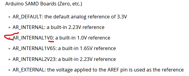
analogReference(AR_INTERNAL1V1);
}
void loop() {
// put your main code here, to run repeatedly:
Serial.print(analogRead(ADC_in));
delay(100);
}
This is all connected to a flexible PCB on the back of the gauge cluster.
The wires are about 5-6".
There's a 12V line that's on when lights are on, this is connect to an Adafruit MPM3610 breakout board which is connected to the 3.3V input on the Feather.
For ground I'm using one of the main ground points on the PCB, it's used for all other gauges on the cluster and is close to the Feather.
I've added the voltage divider to the rest of the circuit I'd posted about in another thread.
Have you tested your feather in another setup? Like a potentiometer connected only to your board ground and 3.3V. If that works well, then it could be that one ground is not good. If on the other hand the problem is due to pure electrical nose, add a big capacitor to the board 12V (100uF) and at the ADC pin (1uF).
I opened the dimmer switch and it's not a rheostat. I'm guessing this is what's causing my issue. I'm hesitant to open it further because the plastic is old and brittle. Guessing with the MOSFET in there it's using PWM? This is in a 91, the gauge cluster had incandescent backlights which I've swapped for some 12V LED modules.
I had a Sparkfun ADS1015 from another project so tested with that.
For the wire I'm trying to read it's pretty reliable when it's off or fully on. Setting the dimmer to not fully off or on gives completely random readings, my multimeter gives me the expected readings.
The ADS1015 breakout board has a 10k pot connected to one input for testing. This channel reads as expected. The board is powered from the 3.3V and ground pins on the Feather.
I did try checking the frequency with my multimeter between ground and the two other pins on this. I'd get readings between 10Hz and 250Hz or so. I've never used it for frequency so not sure if it's the multimeter or this dimmer but the frequency didn't change after connecting probes, disconnecting and reconnecting probes would give a different frequency each time. Turning the dimmer didn't have a reliable effect.
I also tried connecting to a digital input on the Feather but haven't gotten very far with that yet.
Just a thought, (although I doubt it's the issue), but it could be that ADC's sample time is too fast to allow its internal sample capacitor to fully charge for the source resistance provided your voltage divider. Put another way, the voltage divider must provide enough current to charge the ADC's sample capacitor within the sample time period. Lengthening the sample period would give time for the capacitor to charge:
I know that Adafruit's SAMD21 core ADC code is optimised for speed with a shorter sample time, whereas Arduino's is much more conservative, allowing it to accept a wider range input source reistance range. There's a forumula in the back of the SAMD21 datasheet to calculate the maximum source resistance, however if speed isn't a factor it's easier to simply lengthen the sample time in software.
In order to slow down the ADC's sample time to Arduino's more conservative settings just add the following lines in your setup() code:
ADC->SAMPCTRL.bit.SAMPLEN = 0x3f;    // Set max Sampling Time Length to half divided ADC clock pulse (2.66us)
ADC->CTRLB.bit.PRESCALER = ADC_CTRLB_PRESCALER_DIV512_Val;     // Divide Clock ADC GCLK by 512 (48MHz/512 = 93.7kHz)
while(ADC->STATUS.bit.SYNCBUSY);     // Wait for synchronization
Another option, if your input voltage doesn't vary much with time and you're sampling occasionally in the loop() function, would be to put a 100nF capacitor from the microcontroller's analog input pin to ground. This acts as a reservoir, the voltage divider topping up between samples and the capacitor charge providing the required current whenever a sample occurs.
I've made a lot of progress. I hooked up an oscilloscope and found it's PWM at about 215 Hz.
I've adjusted the voltage divider to give 2.2V for the peaks and used this with a digital input.
The only problem with this is I can't differentiate between 0% and 100% duty cycle so I think I'll use an analog input as well to read 0/2.2V.
Thank you for everybody's help, this forum is amazing!