I'm a french student in engineering school (so sorry about my English mistakes), and I'm contacting you today about one of my personals projects.
It is the first time I post something on a forum because I really need help, I'm blocked.
I try for an intelligent remote project to turn On an Arduino Nano board on a pressed button and turn it Off after a scheduled inactivity timer.
To achieve this, I tried the schematics (figure 1) with a button directly linked to the 5v battery that is plugged to the VIn port of the Arduino. For the moment the Arduino power the D5 port with 5v. A transistor base is linked the D5 port to commutate and then enable a power loop. The transistor's collector and emitter are derivates to the button to get the 5v from the battery. I hope it's more or less clear with the Schematic.
However, when I press the button down, the Arduino turn On, the D5 port is high that enable transistor loop and power the board by itself but as soon as I release the button everything shut down. I tried to had a 35v 100uf capacitor to the D5 output to keep some power on release and then continue the loop, but this doesn't work ()Maybe 5v is to low ?).
I stay at your disposal for any unclear information or a complementary one.
Thank you very much for your help,
Your circuit cannot work. You are supplying the base of the transistor from the Arduino, the Arduino gets it's supply from the emitter of the same transistor, so in effect you are just connecting the base to the emitter. The base needs to be fed via a current limiting resistor from a voltage higher than you want the emitter to be. Circuits like this need 2 transistors, either 1 NPN and 1 PNP, or preferably, 1 N channel MOSFET and 1 P channel MOSFET.
Thank you Perry, that was what I supposed.
Can you give a quick schematic or a link with documentation to see the new circuit ?
Thank you very much for your response.
I would but I'm out working and posting on my mobile phone. It will be several hours before I am at my PC. Can you try yourself and post what you think might work?
Please upload to this website, not link to somewhere else.
Ok thank you I will try and send the result here if founded.
I just don't found a direct pictures upload from my computer to this forum that's why I did this way...
As I haven't a license for simulation software I cannot test the circuit (and I don't have PNP transistor too ).
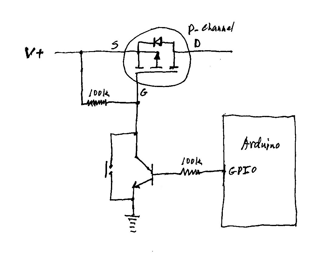
Is this one good ? Or at least closer of the solution ?
Just wondering, why going through all that effort to power down the processor, while in deep sleep it uses <1 µA - so little it's less than the self discharge of most batteries. Those transistors may very well leak more current than a sleeping MCU.
Do you really have a 5V battery? I don't think I've ever seen one. Or is it a powerbank? In any case, if it is 5V, you can't connect it to the Nano's Vin pin. Vin is the input to the 5V regulator, and requires something like 7V to regulate properly. Instead, your 5V supply should be connected to the Nano's 5V pin.
In general, I think it's safer to have your switch connect the collector of the 2N2222 to ground to turn on the power. But that's just a personal preference.
Your circuit looks reasonable, but you should take note of the comment by wvmarle in reply #10, there is no point to doing this, just use the processor's sleep mode. As for the LEDs taking current; turn them off before putting the processor to sleep!
gugzthargy:
It's because the leds consumes about 10mA each (when it's mount on the board)
The power LED of course you just remove... very easy to do. When you're at it, the regulator can go as well. Then the Pro Mini uses virtually no power when in power-down sleep mode.