I am the furthest thing from a technical person but I successfully built a working prototype for a sensor activated, automatic tee system for a golf simulator I’m building. After a LOT of trial and error and research, I got everything working but I decided I wanted to clean it up and make it more “permanent” so I figured I’d up the 22awg jumper wires and breadboard to 18awg and some type of wire terminal. I swapped out all jumper wires with 18awg and plugged into a terminal block breakout I found on Amazon and plugged it into my UNO R3. I thought I had everything hooked up the exact same way but the arduino instantly burnt out and started smoking when I cut on the power. I’m running two 12V DC motors, a 28nema stepper, 3 momentary buttons and a photoelectric proximity sensor. Steppermotor is run through a 32micro-step driver, and the two 12V DC motors are running through an L298N dual bridge. All motors are powered by a DC 12V 40A power supply adapter and I had the arduino powered by a separate power adapter plug hooked up through the VIN and GND. I’m wondering if I didn’t ground everything properly as I pulled all the + and - that were in the breadboard and used 4 port wire connectors ( 1 for the 5V and the + wires and one for all the GND wires. Should I have used a inline circuit terminal block? I really don’t want to solder anything or go the PcB because I have NO IDEA how to do any of that and frankly this is probably my one and only project like this. Any help and tips on considerations for upgrading wires and moving off breadboard would be greatly appreciated. And apologies in advance for post etiquette, I’m sure I’ll get some feedback there ![]() .
.


At a minimum we need to see a schematic or a block diagram showing your connections.
I moved your topic to an appropriate forum category @GolfLife24.
In the future, please take some time to pick the forum category that best suits the subject of your topic. There is an "About the _____ category" topic at the top of each category that explains its purpose.
This is an important part of responsible forum usage, as explained in the "How to get the best out of this forum" guide. The guide contains a lot of other useful information. Please read it.
Thanks in advance for your cooperation.
Without a schematic and wiring diagram it's impossible to be definitive.
However:
- you should not be running you motors through the UNO in any way.
- anything UNO connection that has reasonable short wire runs can use #26 or thinner. I'm sure your solderless breadboard jumpers have a much higher resistance. I measured an 11" jumper at slightly less that 1 ohm.

- Your grounds should look like a "star" with all grounds going to one single point (usually at the power source).


Not sure how old the video is, however today I just design a board, send it off to JLCPCB and received back 5 boards, all for a price less that 2 Starbucks coffees.
I wish I could have done this back in the day!
I guess this is the Holy grail for hobbyists and occasional circuit makers. I think all permanent electronic installations use solder. There isn't really any simple way to turn a breadboard into a PCB without solder. Using "proto PCBS" helps, but still need solder.
With larger gauge wire, screw terminal and common blocks could be used, as long as all your components already have suitable wires attached.
I would suggest the best option is to try soldering, failing that find someone to help building a board.
Otherwise, your approach should work in principle, but without further details impossible to give specific advice. Presumably you mis-wired something, but you already figured that.
Fun fact: "breadboard" circuits used to be nails driven into a piece of board, then wires soldered to the nails. The spring-contact breadboards we use now are actually "solderless breadboard". As a youth I made one such nailed board project.
I guess I recall doing research that said 18AWG or thicker should be used to power DC motors.
This is very interesting…how do I even “send in” my prototype to have something built for me? Sorry, I just can’t wrap my head around this stuff.
Do you have any recommended step by step tutorials on soldering and building PCB from Arduino for beginners?
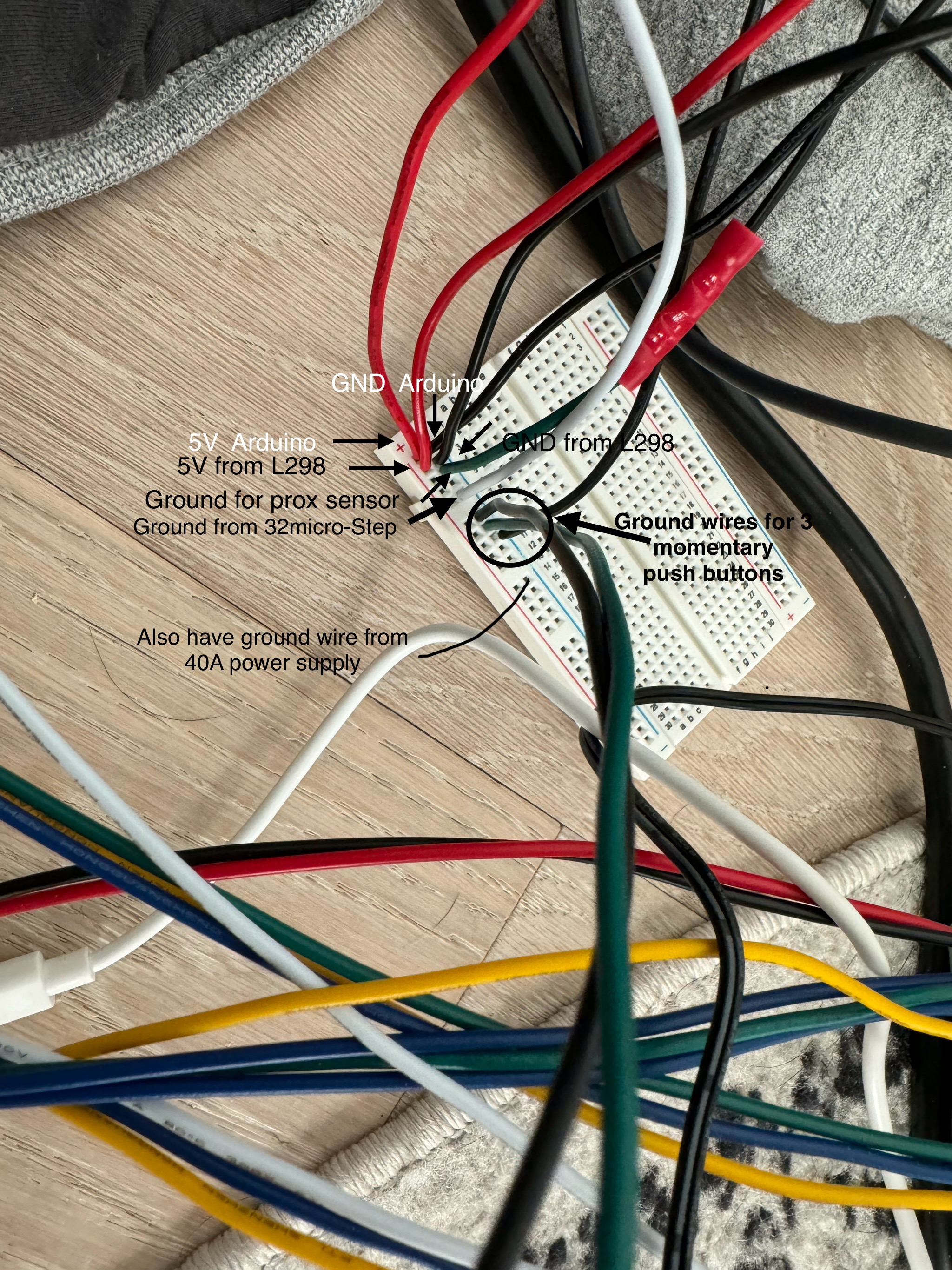
I added some pictures with labels, hopefully it makes sense. ![]()
I added some photos with labels, hope it makes sense.

That's OK. Everybody has to learn sometime.
There are a number of options, all depending on how complex your device might be and what the components are.
From what you've posted it seems your device may not be so complex as to need a full custom printed circuit board. And designing a pcb is probably not a good first step.
I would suggest you consider @LarryD 's suggestion in post 5. And use small already available parts like this driver board.
You might consider if you need the UNO. Perhaps you can get by with a nano (smaller and cheaper)