Hello,
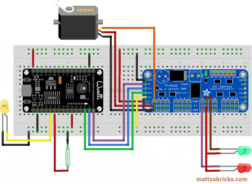
I want to use a ESP8266 to control with pca9685 multiple Servos.
I use this setup: https://mattzobricks.com/wp-content/uploads/2021/12/Wiring-Diagram-MLC-with-PCA9685-0.4_Steckplatine-1024x748.png
When I use this example code everything works:
#include <Wire.h>
#include <Adafruit_PWMServoDriver.h>

// called this way, it uses the default address 0x40
Adafruit_PWMServoDriver pwm = Adafruit_PWMServoDriver();

#define SERVOMIN  150 // This is the 'minimum' pulse length count (out of 4096)
#define SERVOMAX  600 // This is the 'maximum' pulse length count (out of 4096)
#define USMIN  600 // This is the rounded 'minimum' microsecond length based on the minimum pulse of 150
#define USMAX  2400 // This is the rounded 'maximum' microsecond length based on the maximum pulse of 600
#define SERVO_FREQ 50 // Analog servos run at ~50 Hz updates

uint8_t servonum = 1;

void setup() {
  Serial.begin(9600);
  Serial.println("8 channel Servo test!");

  pwm.begin();
  pwm.setOscillatorFrequency(27000000);
  pwm.setPWMFreq(SERVO_FREQ);  // Analog servos run at ~50 Hz updates

  delay(10);
}

void loop() {
  // Drive each servo one at a time using setPWM()
  Serial.println(servonum);
  for (uint16_t pulselen = SERVOMIN; pulselen < SERVOMAX; pulselen++) {
    pwm.setPWM(servonum, 0, pulselen);
  }

  delay(500);
  for (uint16_t pulselen = SERVOMAX; pulselen > SERVOMIN; pulselen--) {
    pwm.setPWM(servonum, 0, pulselen);
  }

  delay(500);

  // Drive each servo one at a time using writeMicroseconds(), it's not precise due to calculation rounding!
  // The writeMicroseconds() function is used to mimic the Arduino Servo library writeMicroseconds() behavior.
  for (uint16_t microsec = USMIN; microsec < USMAX; microsec++) {
    pwm.writeMicroseconds(servonum, microsec);
  }

  delay(500);
  for (uint16_t microsec = USMAX; microsec > USMIN; microsec--) {
    pwm.writeMicroseconds(servonum, microsec);
  }

  delay(500);

  servonum++;
  if (servonum > 7) servonum = 0; // Testing the first 8 servo channels
}
If I integrate the code into mine (see "void receive_packet()" In the area " if (DoCommand == "switch") {"), nothing happens. (Code from the example marked with "//vvTESTPROGRAM" and //^^TESTPROGRAM).
I control the ESP8266 with an app. For the lines "Serial.println(servonum);" something is also displayed in the serial monitor.
Does somebody has any idea?
// Frontend: VB-Projekt "VB NET NodeMCU UDP RS Test"

#include <ESP8266WiFi.h>
#include <WiFiUdp.h>
#include <ESP8266WebServer.h>

//vvTESTPROGRAMM
#include <Wire.h>
#include <Adafruit_PWMServoDriver.h>
Adafruit_PWMServoDriver pwm = Adafruit_PWMServoDriver();
//^^TESTPROGRAMM

ADC_MODE(ADC_VCC);                            // Spannungsmessung

#include <espnow.h>
#include "credentials.h"
#define SERIAL_BAUDRATE     115200

#define ON_Board_LED 16  //  Defining an On Board LED
#define led_built_in_ESP  2
#define UDP_PORT 2000

//vvTESTPROGRAMM
#define SERVOMIN  150 // This is the 'minimum' pulse length count (out of 4096)
#define SERVOMAX  600 // This is the 'maximum' pulse length count (out of 4096)
#define USMIN  600 // This is the rounded 'minimum' microsecond length based on the minimum pulse of 150
#define USMAX  2400 // This is the rounded 'maximum' microsecond length based on the maximum pulse of 600
#define SERVO_FREQ 50 // Analog servos run at ~50 Hz updates
uint8_t servonum = 1;
//^^TESTPROGRAMM

WiFiServer server(80); // Wir richten den Webserver auf Port 80 ein
ESP8266WebServer WebServer(80);

//-------UDP
//char reply[] = "Packet received!";
char packetBuffer[50];
unsigned int localPort = 2000;
WiFiUDP udp;
String strCon;
String SendValue;
//-------UDP

void wifiSetup() {
     // Set WIFI module to STA mode

    WiFi.mode(WIFI_STA);

     // Connect
    Serial.printf("[WIFI] Connecting to %s ", WIFI_SSID);

    WiFi.begin(WIFI_SSID, WIFI_PASS);

    // Wait
    while (WiFi.status() != WL_CONNECTED) {
        Serial.print(".");
        digitalWrite(ON_Board_LED, LOW);
        delay(250);
        digitalWrite(ON_Board_LED, HIGH);
        delay(250);
    }
    Serial.println();

    // Connected!
    digitalWrite(ON_Board_LED, HIGH); //--> Turn off the On Board LED when it is connected to the wifi router.
    Serial.printf("[WIFI] STATION Mode, SSID: %s, IP address: %s\n", WiFi.SSID().c_str(), WiFi.localIP().toString().c_str());
}

void setup() {
      // Init serial port and clean garbage
    Serial.begin(SERIAL_BAUDRATE);
    Serial.println();

    pinMode(ON_Board_LED,OUTPUT);
    pinMode(led_built_in_ESP, OUTPUT);
    digitalWrite(ON_Board_LED, HIGH); //--> Turn off Led On Board
    digitalWrite(led_built_in_ESP, HIGH);

    // Wifi
    wifiSetup();
    digitalWrite(led_built_in_ESP, HIGH);

    udp.begin(localPort);
    server.begin();
    Serial.printf("Webserver gestartet, öffnen Sie %s in einem Webbrowser\n", WiFi.localIP().toString().c_str());
//vvTESTPROGRAMM
    pwm.begin();
    pwm.setOscillatorFrequency(27000000);
    pwm.setPWMFreq(SERVO_FREQ);  // Analog servos run at ~50 Hz updates

    delay(10);
//^^TESTPROGRAMM
}

// Inhalt der Webseite generieren
String prepareHtmlPage()
{
  String htmlPage =
     String("HTTP/1.1 200 OK\r\n") +
            "Content-Type: text/html\r\n" +
            "Connection: close\r\n" +  // Die Verbindung wird nach der Übertragung geschlossen
            //"Refresh: 5\r\n" +  // Automatisch alle 5 Sekunden neu laden
            "\r\n" +
            "<!DOCTYPE HTML>" +
            "<html>" + SendValue + "</html>" +
            "\r\n";
  return htmlPage;
}

void loop()
{
  AktWebsite();
  receive_packet();
  WebServer.handleClient();
}

void AktWebsite() {
  WiFiClient client = server.available();
  // warten auf Verbindung vom Client (Webbrowser)
  if (client)
  {
    Serial.println("\n[Client hat sich verbunden]");
    while (client.connected())
    {
      // zeilenweise einlesen was der Client (Webbrowser) anfragt
      if (client.available())
      {
        String line = client.readStringUntil('\r');
        Serial.print(line);
        // bis zum Ende der Anfrage warten (=Leerzeile)
        if (line.length() == 1 && line[0] == '\n')
        {
          SendValue = ReturnString();
          client.println(prepareHtmlPage()); // Antwort ausgeben
          break;
        }
      }
    }
    delay(1000); // dem Browser Zeit geben um die Antwort zu empfangen
    // Die Verbindung schließen:
    client.stop();
    Serial.println("[Client getrennt]");
    delay(10);
  }
}

String ReturnString() {
  String strRailroadControl = "RailroadControlModule";
  String strRailroadControlType = "SwitchModule";
  int Spannung = ESP.getVcc();
  String strSpannung = String(Spannung);
  unsigned int myChipId = ESP.getChipId();
  String StrMyChipId = String(myChipId);
  // [0]Identifikation als Komartibles Modul;[1]Art des Moduls;[2]Spannung;[3]Chip-ID
  return strRailroadControl + ";" + strRailroadControlType + ";" + strSpannung + ";" + StrMyChipId;
}

String getValue(String data, char separator, int index)
{
  int found = 0;
  int strIndex[] = { 0, -1  };
  int maxIndex = data.length() - 1;
  for (int i = 0; i <= maxIndex && found <= index; i++) {
    if (data.charAt(i) == separator || i == maxIndex) {
      found++;
      strIndex[0] = strIndex[1] + 1;
      strIndex[1] = (i == maxIndex) ? i + 1 : i;
    }
  }
  return found > index ? data.substring(strIndex[0], strIndex[1]) : "";
}

void receive_packet() {
  int packetSize = udp.parsePacket();
  if (packetSize) {
    IPAddress remoteIp = udp.remoteIP();
    int len = udp.read(packetBuffer, 255);
    if (len > 0) packetBuffer[len] = 0;
    strCon = packetBuffer;
    // Serial.println(strCon); //Kommentierung rausnehmen zum testen
    // Eingehenden String parsen in Befehl, Wert und ggf. Pin

    String DoCommand = getValue(strCon, ';', 0);
    int DoValue = getValue(strCon, ';', 1).toInt();
    String DoServo = getValue(strCon, ';', 2);
    Serial.println(DoValue);
    // Komplexe Befehle (String Inhalt des Dateneingangs: BEFEHL(string);BEFEHLEWERT(int);PIN(string)
    if (DoCommand == "switch") {

//vvTESTPROGRAMM

  Serial.println(servonum);
  for (uint16_t pulselen = SERVOMIN; pulselen < SERVOMAX; pulselen++) {
    pwm.setPWM(servonum, 0, pulselen);
  }

  delay(500);
  for (uint16_t pulselen = SERVOMAX; pulselen > SERVOMIN; pulselen--) {
    pwm.setPWM(servonum, 0, pulselen);
  }

  delay(500);

  // Drive each servo one at a time using writeMicroseconds(), it's not precise due to calculation rounding!
  // The writeMicroseconds() function is used to mimic the Arduino Servo library writeMicroseconds() behavior.
  for (uint16_t microsec = USMIN; microsec < USMAX; microsec++) {
    pwm.writeMicroseconds(servonum, microsec);
  }

  delay(500);
  for (uint16_t microsec = USMAX; microsec > USMIN; microsec--) {
    pwm.writeMicroseconds(servonum, microsec);
  }

  delay(500);

  servonum++;
  if (servonum > 7) servonum = 0; // Testing the first 8 servo channels
//^^TESTPROGRAMM
    } else if (DoCommand=="SendStatus") {           // Identifizierung als Node8266 beim IP-Scan im FE
      // Send return packet
      SendValue = ReturnString();
      AktWebsite();
    }
    delay(1000); // Schutz um nicht alle gleichzeitig zu schalten.
  }
}
