Hi! This is my first post and I'm new to Arduino since yesterday.
I have a question about the use of the ADC on my MKR1010 board, but it is probably not specific to MKR1010.
I did quick test yesterday with an idea I have on how to create a water level sensor for my pool. It worked directly, but... I really don't know why it is working?! My idea is simple: measure the resistance (ohm) in the water by having to electrodes (actually two nails in my prototype) down in the water. When one (or both) of the electrodes (nails) is above the water surface, the circuit is broken; hence water can be detected. Ok, I know that there are float sensors that can do the same, but for my application, my solution with measuring the water resistance (or actually detecting 0 ohm - short circuit) works better.
Now to my confusion. When I started investigating how to measure "ohm", I looked at two different Arduino projects: 1) the basic one about reading a potentiometer and 2) the ohm meter project (one known resistor and the "unknown" to measure).
For my application, I went for the ohm-meter project... but I accidentally routed my wires wrong so the resistor and +5 volt weren't connected at all! Every thing works without the +5 volt... The circuit looks like following:
Electrodes are put in a glass of water, the circuit is unbroken.
I'm getting values such as 0 to 10 from the 10-bits ADC when both electrodes are in the water, which is perfectly well (I take the mean value from several samples and then have a threshold variable to deal with the almost zero values).
So, can I go with this circuit or should use one resistor and the +5 volt line? Why does it work? Is it wrong?
A floating input will pick up static electrical charge from the environment. It is not "working" as an Ohmmeter.
Use the resistor and connect to 5V as instructed. However, be aware that the circuit is not stable and the probe will undergo corrosion in a short time.
I'm not really interested in measuring the resistance of the water, but really detect when the circuit is unbroken (when a small current is going between the two nails).
You are of course right in that the floating input is picking up electrical charge from the environment.
I will try using with the resistor and 5V. Yes, I know it will under go corrosion with time.
If A0 and GND have electrical contact in the water (i.e short circuit), the water level is too high
If A1 and GND have electrical contact in the water (i.e short circuit), the water level is good
Else (circuit broken), the water is too low!
I tried adding the 3.3v and the resistor as follows:
3.3v ---> R ---> A0 ---> electrode 1
3.3v ---> R ---> A1 ---> electrode 2
GND ------> electrode 3
(really bad picture of a circuit, hope you get it anyway)
The problem with the above circuit is that the two ADCs inputs interfere with each other. For instance, when both A0 and A1 are in the water at the same time, the values are a bit higher than when just one is in.
I have probably misunderstood how to use the A/D converters.
I have tried different values on R, but always the same value for R on both resistors. Higher R works better, but it works even better without any resistor and the 3V line!!!
Could anyone show me how to connect the circuit properly?
If you have applied 5V to a 3.3V input, that input is probably fried.
In general you need two resistors, one from 3.3V to each ADC input, and each input is also connected to one probe. That way the two ADC input voltages are independent.
jremington:
If you have applied 5V to a 3.3V input, that input is probably fried.
I haven't applied 5V to 3.3V input.
jremington:
In general you need two resistors, one from 3.3V to each ADC input, and each input is also connected to one probe. That way the two ADC input voltages are independent.
That is actually what I have been doing... GND is common, but other than that. Can you please show me a circuit?
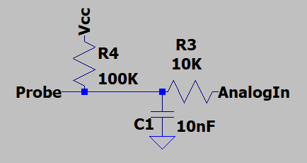
Because those probes are exposed to the outside world, you should have some protection against overvoltage, and negative voltages on the analog inputs. The circuit below will be better than nothing.
Also, after switching ADC channels, read the input twice and discard the first value. On some microprocessors, residual charge on the sampling capacitor will cause cross talk between channels.
The probes should not be in a line. That way current flow from the upper probe to ground should have less to no effect on the lower probe reading.
Finally, you reduce probe corrosion and eliminate the above problem by turning on "Vcc" only when making a measurement. Use an output port pin (one for each probe) set to HIGH just before making a reading, to power the probe instead of Vcc. I would put a "delay(5)" statement after setting the port pin HIGH, to allow C1 to charge.