I have been having a vo;ltage problem with a MAX7219 led board.
When I apply 4.8v from my PC to the usb port, one time I get 4.78v, then another time I get 2.2v and then 1.8v , and now it's down to 1.5v, even with nothing connected to the board.
It's like something is draining the volage, or is it the Arduino which is at fault
Is there any way of troubleshooting this volatge problem or should I scrap the Arduino.
avalon66:
I have been having a vo;ltage problem with a MAX7219 led board.
When I apply 4.8v from my PC to the usb port, one time I get 4.78v, then another time I get 2.2v and then 1.8v , and now it's down to 1.5v, even with nothing connected to the board.
It's like something is draining the volage, or is it the Arduino which is at fault
Is there any way of troubleshooting this volatge problem or should I scrap the Arduino.
Thanks
There is no way to help you with trouble shooting when we can't see what you are working with. A schematic is necessary.
Ok thanks, and here is a schematic of what I intend to do. As it is part of a project, I didn't think I could upload files.
Nowit has made a liar of me as it si now stable at 4.8v with everything connected. Tghe problem is though that the MAX7219 led board won't work at the violtage, and seems to be ok at 1.8v.
Now I am powering it with a 5v 2.5a power supply now but the display does not light up. I have a 5v 6amp power supply which I could try, or would that be too much amperage.
Yes, all grounds go back to the GND socket next to Pin13 .on the Arduino .
The LED lights come on when it is powered up, but then goes off straight away.
Measuring the voltage on the breadboard shows 4.82 initially and the led lights come on, then rises to 5.18 rapidly, and the led lights go off.
Just for 1 instant the voltage did not go over 5v, and the lights stayed on, but there was no controll over them with the buttons as per the schematic I posted yesterday.
More:
After I changed over to another breadboard and plugged in the USB cable, it stayed at around 3.1v and the led lights came on, but still no control of them with the buttons. The second time I tried , the lights cam on while the voltsage was reading 3.1v, but went off as the voltage rose to 4.7.
It seems that anything over 3.2 volts, the MAX7219 doesn't work, very strange, as it is supposed to handle 5v.
Yes I know what I have said is contradictory, but that is what I am seeing.
I have connected the MAX7219 directly to the Arduino Uno and using the usb cable from pc to power it.
The PC is putting 3.75 volts out, and the lights on the MAX7219 are on, and I have also disconnected the clk, din and cs wires from the digital output pins.
Measuring the voltage across the vcc and gnd of the MAX7219 I get 2.5v nominaly.
When I use the 5v 2.5a power supply I get roughly a 5v reading across the same pins.
Connecting the clk wire to pin 13 on the Arduino, I now get 2.15v
Connecting the cs wire to pin 11, I get 2.0v
Connecting the din wire to pin 10, tjhe MAX7219 comes on then off again
I then connected the din wire to digital pin 6 on the arduino, and the MAX7219 stays on, but the voltage is now down to 1.8v
All the above measurments were taken with the usb cable from pc plugged into the arduino uno.
The measurements were roughly the same when I used the 5v 2.5a power supply.
Can ayone please tell me where the fault is and what needs to be done to correct it
avalon66:
Measuring the voltage on the breadboard shows 4.82 initially and the led lights come on, then rises to 5.18 rapidly, and the led lights go off.
Just for 1 instant the voltage did not go over 5v, and the lights stayed on, but there was no controll over them with the buttons as per the schematic I posted yesterday.
More:
After I changed over to another breadboard and plugged in the USB cable, it stayed at around 3.1v and the led lights came on, but still no control of them with the buttons. The second time I tried , the lights cam on while the voltsage was reading 3.1v, but went off as the voltage rose to 4.7.
It seems that anything over 3.2 volts, the MAX7219 doesn't work, very strange, as it is supposed to handle 5v.
Yes I know what I have said is contradictory, but that is what I am seeing.
You aren't putting all the LED current through the breadboard are you.
This would explain the inconsistent and varying voltages.
Between what points are you measuring your voltages?
You should be using the negative terminal of the power supply as your gnd reference.
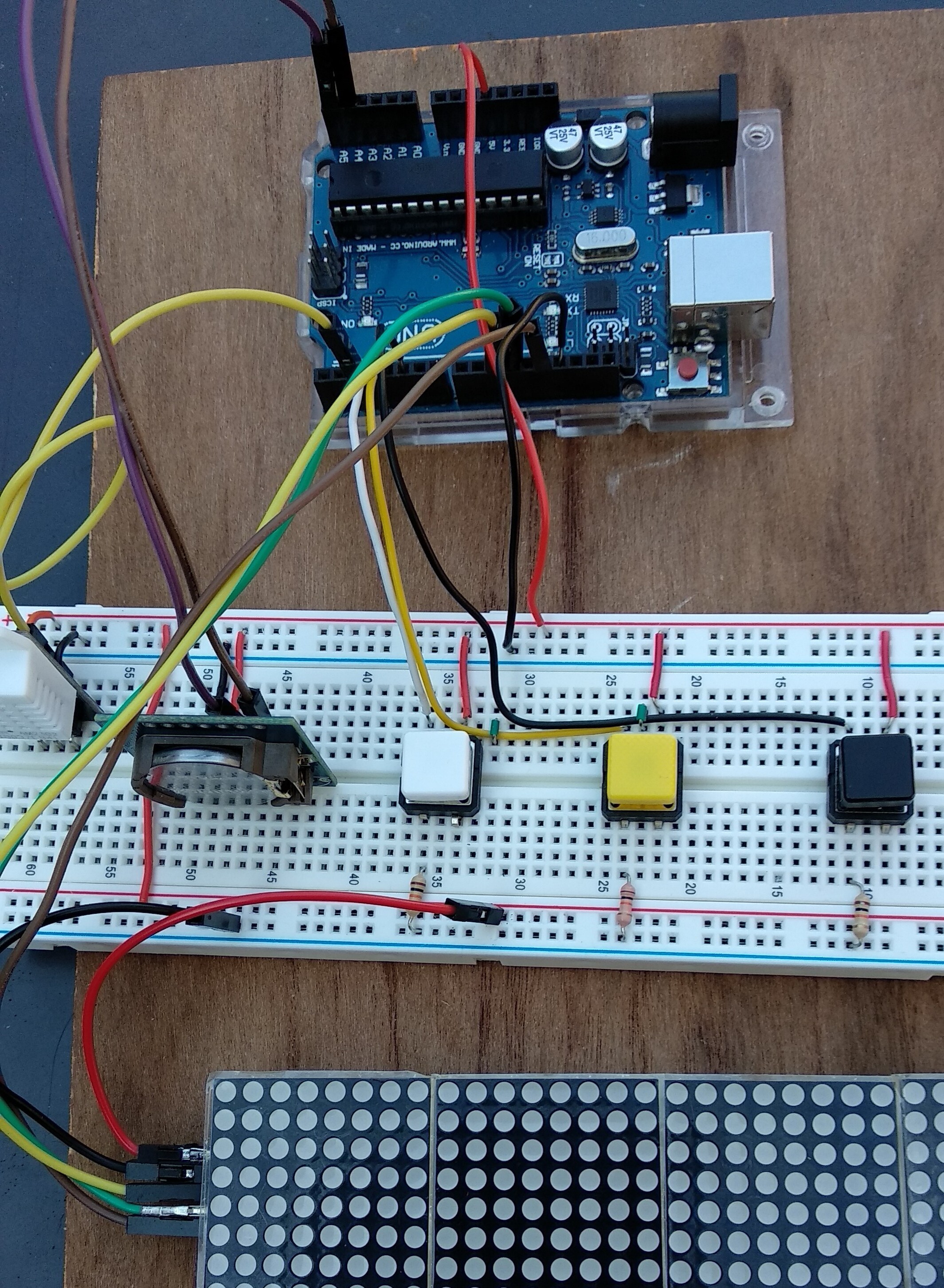
Can you post a picture of your project please?
So we can see your component layout.
Tom...
I am wiring the components as per the schematic on the website for the project which is included here
The picture of the parts etc shows most things except where the 2 wires for vcc and gnd go to the 5v and gnd on the arduino, and the DS1307RTC SDA and SCL wires go to A4 and A5 respectivly on the Arduino.
The parts used are on a new K&H AD-102 breadboard, which arrived earlier.
After I uploaded a picture of my setup, I checked it and found that I had 2 wires from the DS1307RTC in the wrong pins as it were, I had the DIN and CS the wrong way round. That is now corrected.
Also, the new K & H Ad-102 breadboard, unbeknowns to me earlier, there is a break in both vcc and gnd rails on both sides, yet on the cheapo breadboards there is no break on either side.
Now the project is working but I can't make any sense of what it is displaying.
That might have something to do with the missing wire. You're schematic shows a wire from pin 10 (SS on the Arduino) going to the display. That is missing the photo you posted of your actual setup.
I've got it all working now as I oredered another MAX7219 from The Micro Hut and it is showing text and numbers the right way up, which the other one did not.
At first the new MAX7219 lit up and was working as it should, but more lately, in the last couple of hours, it powers up, then goes off. Sometimes 1 or 2 of the segments light up and stay that way, while the other 2 display text/numbers.
The voltage in that state is 3.4/3.5 volts, and when it goes off the voltage is 4.77 volts from a 5v 2.5amp power supply.
It seems it will only work when the voltage is around 3.2/ 3.3 volts, and if it rises to more than 3.4 the MAx7219 goes off.
Can anyone shed some light on why this is happening
Hi,
If that voltage reading is the 5V supply, then it is overloading, and current limiting.
The voltage goes back up to 4.77V because the display has gone OFF and the load current drops.
Can you post a wider picture of your project so we can see ALL your components please?
Can you hand draw YOUR circuit?
Reverse engineer what you have built, DO NOT use the one you have posted.
Can you program your code so that ONLY one digit is displaying?
Can you please post your code?
What brightness level have you got it set for?
If full brightness, then try about 1/4 of full brightness.
Sorry I can't program the code as I don't really know what to do to get just one digit is displaying, and it is not my code. I downloded it from here:
As far as I know, the brightness level is set by one of the buttons, the one that goes to pin 3. When it came on, the brightness was at a default setting, presumably in the code.
I can't post a picture of the layout together with the picture of the layout and the code, as it is too big, but I could post it after your reply to this.
I used a HB pencil to draw the layout of wires and parts, and hope it is clear enough to make sense of.
I have since tried another arduino , no change, then another breadboard, no change, and then wired the MAX7219 direct to the arduino 5v and gnd pins, where the MAX7219 lit up all 4 blocks.
I've also changed the ATMega chip just in case that was faulty, and when I powered it up, the MAX7219 lit up, but when I uploaded the sketch/code to it, the MAX7219 went off.