Hello
I'm currently trying to adjust the current limit for my NEMA17 steppermotor but I can't measure anything. I'm sure that I connected everything correctly, but my device still doesn't measure anything. I'm using a steppermotor with a nominal current of 2,5 A, but I have a 12 V 2 A adapter, perhaps this is the issue, not to mention that I also have a setup connected to the same adapter that als draw not much but some power like mini servo's Arduino etc. Could someone help me out?
Hi,
Can you please post a schematic of your project?
Can you please post your code in code tags?
Some images of your project may help also.
Please post a link to spec/data of your stepper, Nema17 only tells us the physical size and nothing about its electrical parameters.
What is your 12V 2A adapter?
What are you measuring?
Thanks.. Tom.. ![]()
![]()
![]()
![]()
You almost certainly don't need to run the stepper at 2.5 amps! I'd suggest you try 1 amp and see how it goes. Look at the video on the pololu site in the 8825 sectio for instructions on setting the current. You can have the motor disconnected to set the voltage, don't connect or disconnect while powered up though. Also watch the video to the end where it explains why the supply current is significantly less than the motor current you set.
I don't have a code yet for the steppermotor.
The link to the datahsheet is SMNM17S18KG48.pdf (reprapworld.nl).
The adapter is just a simple ac/dc converter with a male dc jack connected to my Arduino Uno.
I'm measuring the trimmer and GND for the Vref.
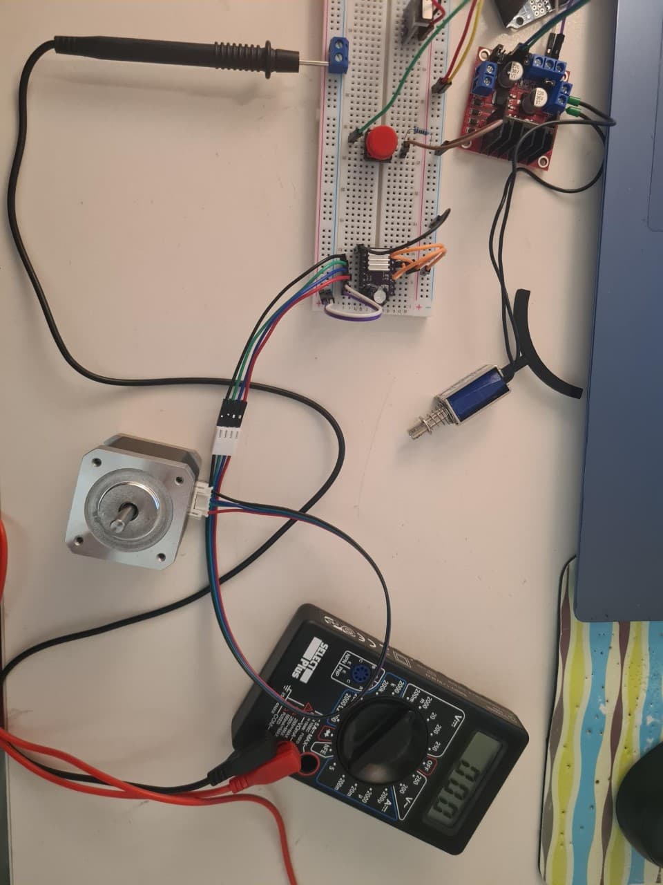
Obviously in this picture the red wire is not connected to the trimmer because I don't have crocodile connectors, but it still doesn't measure the V ref if it's connected.
Is the motor getting warm? The best place to see the voltage is on the slider on the trimpot. Touch your probe on that, it may actually be set to zero.
No the motor is still cold, the slider of the trimmer is still zero.
Tweak the slider a little clockwise and see if you can see a voltage. Are you sure there is a supply to the driver?
Yes, I'm assuming the driver has burned, because the steppermotor used to make a noise when it was connected and now it doesn't also there is no 12 V voltage between 1A-2A and 1B-2B.
Hi,
No code, no drive.
You must code your controller so it can pass on signals to drive your stepper.
PLEASE draw a schematic.
Can you please post a copy of your circuit, in CAD or a picture of a hand drawn circuit in jpg, png?
Hand drawn and photographed is perfectly acceptable.
Please include ALL hardware, component names and pin labels.
What model Arduino are you using?
Tom.... ![]()
![]()
![]()
![]()
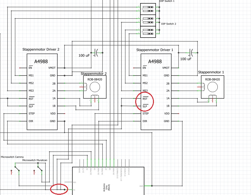
It's an Arduino Uno. I'm don't want to drive it yet because it's Vref isn't adjusted, that is the next step. Here is a drawing I made on Fritzing.

P.S. The driver is still a DRV8825 but I used A4988 because Fritzing doesn't have a DRV8825 so don't let it confuse you.
Hi,
What do you mean?
I hope you are going to develop your code in stages, with JUST driving ONE stepper back and forth as probably your first step.
What is "transportbandmotor" and what does the 5K pot to do with it.
Can I suggest you draw a simple circuit to drive the motor driver and get that working,
FOR THE MOMENT FORGET ABOUT THE REST, the more hardware you add at this stage, the harder it will be to fix bugs, program bugs and hardware bugs.
A more complex schematic will develop as you add and debug in stages.
Can Fritzy schematic EXPORT a jpg?
The diagram you posted is not of very clear, resolution is not high enough.
Thanks.. Tom.. ![]()
![]()
![]()
![]()
Yes my code has been developed in stages and my two steppermotors are the last step of my total code. Transbortbandmotor is just a DC motor. All of the other hardware has been debugged and I just need to add the code of my steppermotor. I'll make a smaller and a clearer screenshot of the circuit for the two steppermotors.

Hi,
Sorry not being able to see how you have it connected to the DC motor drive and a 5K potentiometer.
That circuit in post#13 was only partial.
Why do you have RST and SLP bar, connected to A5 of the UNO.
I think you would be better to reverse engineer your project to get an accurate diagram.
Thanks... Tom.... ![]()
![]()
![]()
There is nothing connected to the A4988 VDD pin.
It's a DRV8825 in reality. I left it disconnected because it is the fault pin.
It's actually the 5 V pin, but it looks like A5 because it is upside down.
PLEASE draw your circuit, an image of a hand drawn circuit will be fine.
Tom... ![]()
![]()
![]()
![]()


