So I am building a watering system for my plant for when I go to Uni, the hardware includes an Arduino Uno Wifi R2, a relay, breadboard, bunch of wires and obviously a pump!
The relay that I have bought requires a 12v to operate it, below is the link to the website I bought it from:
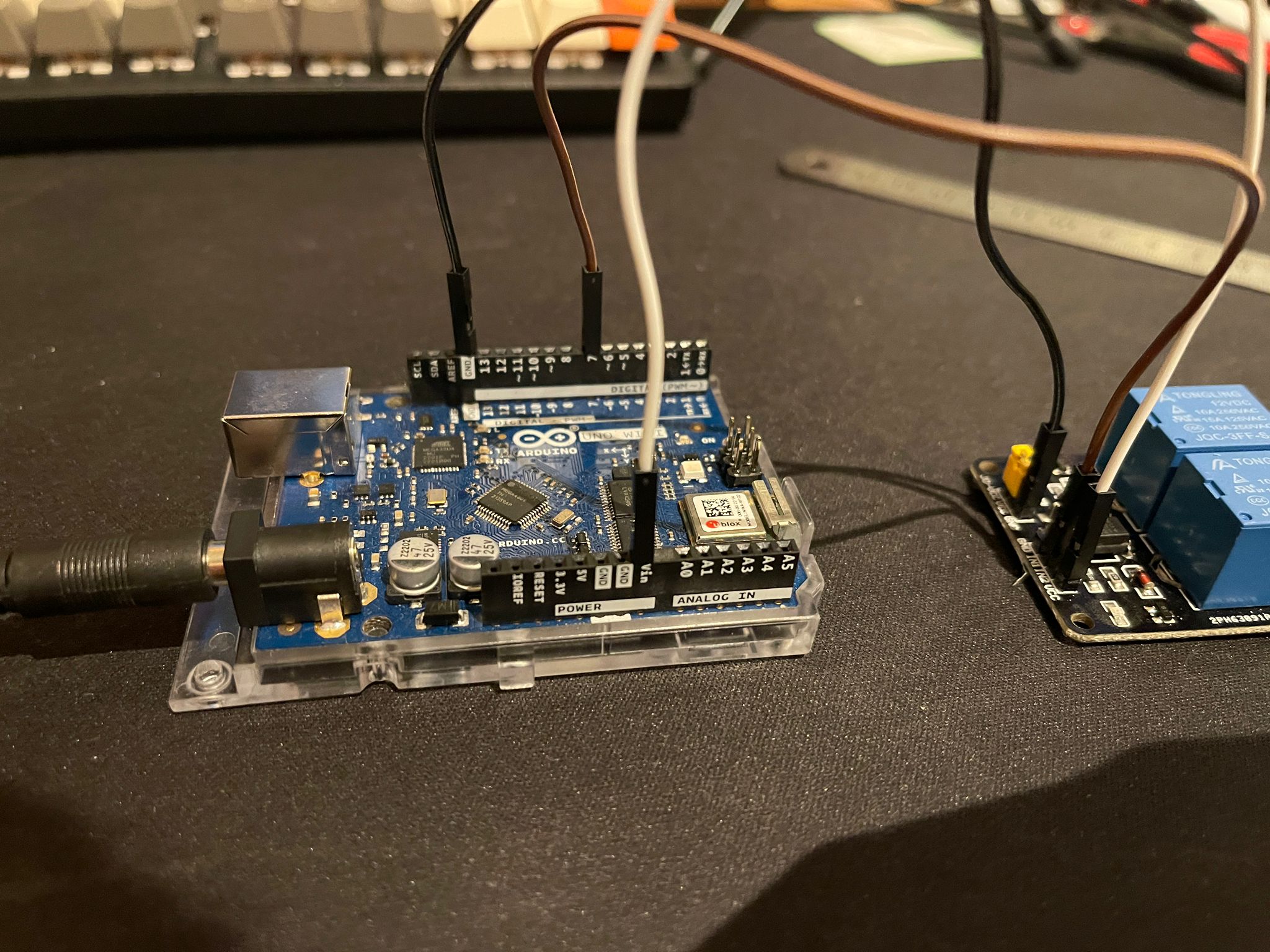
So I have connected the netural wire of my pump to the NO and COM side of the relay, I have also used Vin as my 12v for VCC, IN1 is Pin 7 and Ground is ground.
Now the problem, when I have connected everything together and run the code, the pump is on continuously without stopping and I am not sure why, even if I have done everything the wrong way round it should run for 30 seconds and stop for 5. I do not think that my code is incorrect (althought I am a newbie so please forgive me if it is) as I have tested it using a LED light. I know that the relay operates because it has a light on whenever it makes a connection and it does make a clicky sound when it makes the connection.
Too Long Didn't Read?
My relay isn't working correctly, might be because of my awful code (but I have tested it out with an LED) might also because of awful wiring. Honestly have no idea.
Vin is not a power output. How does one get 12V out of Vin?
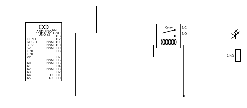
Please post a schematic. Written descriptions are always more ambiguous than a drawing. Hand drawn, photographed and posted is fine. Include all pin names/numbers, components, their part numbers and/or values and power supplies.
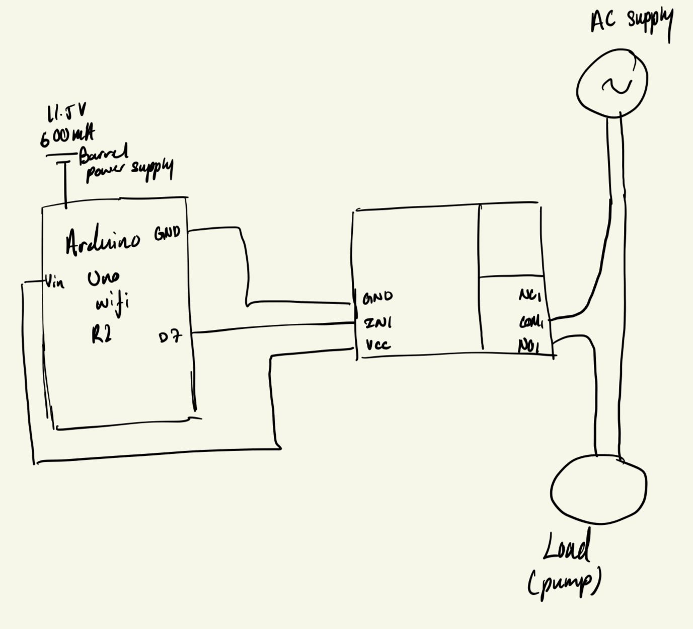
For the 12v, I have connected my arduino to a barrel jack and that provides 11.5V (so I lied a little it's not fully 12V)
As for the schematics, I am not sure what you mean but I will include the photos and also the simulation that I have done here:
The pump is not connected to the relay right now because I can hear the relay physically turning on and off and I don't wanna risk electrocuting myself
I had a look at the schematic in that manual, which I see is for the 5v relay version. Just looking at your pictures it looks like you have12 volts connected to the relay board “VCC” terminal. You should only put the 5 volt VCC from the Uno to that terminal. Remove the jumper between VCC and RY-VCC. Then plug the12 volts into RY-VCC. the way it appears to be wired you are switching 12 volt through the Uno pin. Your pin or the entire chip may already be damaged.
I see in your pictures that you have JD-VCC instead of RY-VCC.
There are a lot of tutorials etc explaining what a schematic is and how to create one. KiCad is free and a very good program. Simply stated a schematic is the language of electronics. One schematic would convey a lot more information than your pictures did and no googling parts that are not familiar.
Looking at the Uno R3 schematic, the Vin pin is powered from the power input jack through a diode. So the Vin will also act as a power source when the board is powered from the jack
So I don't think the code is the problem because if it is the logic that is the inverted surly it should turn on for 30 seconds and then off for 5 seconds and so on rather than off for 30 seconds and on for 5 seconds? So when I tested it with the pump originally, the pump would just run continuously.
As for the wiring, I have followed what you have said and it still doesn't seem to work. I have also checked that to make sure that the Vin pin which supply the 12v is still working and the relay is also still working.
I wasn't able to find a pump in the schematic app that I was using.
Not shorting the circuit as it was connected to NO meaning that it would normally be open unless I've put in a small current and the electromagnet close the loop.
The pump was connected to the mains when I was testing out the code so I can see that the pump is running
Watch this video which just came across my YouTube
In your schematic you are still connecting the 12 volts to the wrong point, unless that does not reflect what you are doing now. The 12 volts must be connected to the JD-VCC, not VCC. The 5 volts from the Uno should be connected to VCC.
The video explains it very clearly. I very briefly had the wrong link inserted. Looks right now.
The video also is using the 5 volt relay version while you are using a 12 volt version. It is essential that you connect the 12 volts to JD-VCC to prevent damage to your uno. Also remove the jumper between JD-VCC and VCC.
I like your schematics, even though the computer drawn one does not reflect the board you are using. The manual I linked in post No. 5 has the schematic for your board with the exception of the 5 volts for JD-VCC. you need 12 volts there.
Thank you so much for the video, he explained it very well! I have gotten my red LED to flash like he did but the relay doesn't work until I have connected my Vin from my Arduino to JD-VCC, I know he said that it is good practice to have a separate power source for will it do any harm to connect my Vin to JD-VCC?
As I mentioned in post #7, the Vin pin will act as a power output as long as you are using the power jack as your input for power to the Uno. The voltage will be about 0.7 volts less than the 12 volt (11.5 volt?) input to the jack due to the voltage drop across the diode I mentioned. This should still be enough voltage to allow the relays to operate.
It would be better to directly connect 12 volts to JD-VCC though. I don’t know what the rating of the diode is. You should unplug that 12 volt supply from the Uno when you are plugged into your computer for programming to avoid damaging the USB port or your computer.